Legal Notice
Copyright © 2010 Red Hat Inc..
The text of and illustrations in this document are licensed by Red Hat
under a Creative Commons Attribution–Share Alike 3.0 Unported license
("CC-BY-SA"). An explanation of CC-BY-SA is available at
http://creativecommons.org/licenses/by-sa/3.0/.
In accordance with CC-BY-SA, if you distribute this document or an
adaptation of it, you must provide the URL for the original version.
Red Hat, as the licensor of this document, waives the right to
enforce, and agrees not to assert, Section 4d of CC-BY-SA to the fullest
extent permitted by applicable law.
Red Hat, Red Hat Enterprise Linux, the Shadowman logo, JBoss,
MetaMatrix, Fedora, the Infinity Logo, and RHCE are trademarks of Red
Hat, Inc., registered in the United States and other countries.
Linux® is the registered trademark of Linus Torvalds in the United States and other countries.
Java® is a registered trademark of Oracle and/or its affiliates.
XFS® is a trademark of Silicon Graphics International Corp. or its subsidiaries in the United States and/or other countries.
MySQL® is a registered trademark of MySQL AB in the United States, the European Union and other countries.
All other trademarks are the property of their respective owners.
1801 Varsity Drive
Raleigh, NC 27606-2072 USA
Phone: +1 919 754 3700
Phone: 888 733 4281
Fax: +1 919 754 3701
This document provides information about installing, configuring and
managing Red Hat High Availability Add-On components. Red Hat High
Availability Add-On components allow you to connect a group of computers
(called nodes or members) to work together as a cluster. In this document, the use of the word cluster or clusters is used to refer to a group of computers running the Red Hat High Availability Add-On.
The audience of this document should have advanced working knowledge
of Red Hat Enterprise Linux and understand the concepts of clusters,
storage, and server computing.
This document is organized as follows:
For more information about Red Hat Enterprise Linux 6, refer to the following resources:
Red Hat Enterprise Linux Installation Guide — Provides information regarding installation of Red Hat Enterprise Linux 6.
Red Hat Enterprise Linux Deployment Guide — Provides information regarding the deployment, configuration and administration of Red Hat Enterprise Linux 6.
For more information about the High Availability Add-On and related
products for Red Hat Enterprise Linux 6, refer to the following
resources:
Red Hat Cluster Suite Overview — Provides a high-level overview of the High Availability Add-On, Resilient Storage Add-On, and the Load Balancer Add-On.
Logical Volume Manager Administration — Provides a description of the Logical Volume Manager (LVM), including information on running LVM in a clustered environment.
Global File System 2: Configuration and Administration
— Provides information about installing, configuring, and maintaining
Red Hat GFS2 (Red Hat Global File System 2), which is included in the
Resilient Storage Add-On.
DM Multipath — Provides information about using the Device-Mapper Multipath feature of Red Hat Enterprise Linux 6.
Linux Virtual Server Administration —
Provides information on configuring high-performance systems and
services with the Red Hat Load Balancer Add-On (Formerly known as Linux
Virtual Server [LVS]).
Release Notes — Provides information about the current release of Red Hat products.
High Availability Add-On documentation and other Red Hat documents are
available in HTML, PDF, and RPM versions on the Red Hat Enterprise
Linux Documentation CD and online at
http://docs.redhat.com/.
This manual uses several conventions to highlight certain words and
phrases and draw attention to specific pieces of information.
In PDF and paper editions, this manual uses typefaces drawn from the
Liberation Fonts
set. The Liberation Fonts set is also used in HTML editions if the set
is installed on your system. If not, alternative but equivalent
typefaces are displayed. Note: Red Hat Enterprise Linux 5 and later
includes the Liberation Fonts set by default.
1.1. Typographic Conventions
Four typographic conventions are used to call attention to specific
words and phrases. These conventions, and the circumstances they apply
to, are as follows.
Mono-spaced Bold
Used to highlight system input, including shell commands, file names
and paths. Also used to highlight keycaps and key combinations. For
example:
To see the contents of the file my_next_bestselling_novel in your current working directory, enter the cat my_next_bestselling_novel command at the shell prompt and press Enter to execute the command.
The above includes a file name, a shell command and a keycap, all
presented in mono-spaced bold and all distinguishable thanks to context.
Key combinations can be distinguished from keycaps by the hyphen connecting each part of a key combination. For example:
Press Enter to execute the command.
Press Ctrl+Alt+F2 to switch to the first virtual terminal. Press Ctrl+Alt+F1 to return to your X-Windows session.
The first paragraph highlights the particular keycap to press. The
second highlights two key combinations (each a set of three keycaps with
each set pressed simultaneously).
If source code is discussed, class names, methods, functions,
variable names and returned values mentioned within a paragraph will be
presented as above, in mono-spaced bold. For example:
File-related classes include filesystem for file systems, file for files, and dir for directories. Each class has its own associated set of permissions.
Proportional Bold
This denotes words or phrases encountered on a system, including
application names; dialog box text; labeled buttons; check-box and radio
button labels; menu titles and sub-menu titles. For example:
Choose → → from the main menu bar to launch Mouse Preferences. In the Buttons tab, click the Left-handed mouse check box and click Close to switch the primary mouse button from the left to the right (making the mouse suitable for use in the left hand).
To insert a special character into a gedit file, choose → → from the main menu bar. Next, choose → from the Character Map menu bar, type the name of the character in the Search field and click Next. The character you sought will be highlighted in the Character Table. Double-click this highlighted character to place it in the Text to copy field and then click the Copy button. Now switch back to your document and choose → from the gedit menu bar.
The above text includes application names; system-wide menu names and
items; application-specific menu names; and buttons and text found
within a GUI interface, all presented in proportional bold and all
distinguishable by context.
Mono-spaced Bold ItalicProportional Bold Italic
Whether mono-spaced bold or proportional bold, the addition of
italics indicates replaceable or variable text. Italics denotes text you
do not input literally or displayed text that changes depending on
circumstance. For example:
To connect to a remote machine using ssh, type ssh username@domain.name at a shell prompt. If the remote machine is example.com and your username on that machine is john, type ssh john@example.com.
The mount -o remount file-system command remounts the named file system. For example, to remount the /home file system, the command is mount -o remount /home.
To see the version of a currently installed package, use the rpm -q package command. It will return a result as follows: package-version-release
Note the words in bold italics above — username, domain.name,
file-system, package, version and release. Each word is a placeholder,
either for text you enter when issuing a command or for text displayed
by the system.
Aside from standard usage for presenting the title of a work, italics
denotes the first use of a new and important term. For example:
Publican is a DocBook publishing system.
1.2. Pull-quote Conventions
Terminal output and source code listings are set off visually from the surrounding text.
Output sent to a terminal is set in mono-spaced roman and presented thus:
books        Desktop   documentation  drafts  mss    photos   stuff  svn
books_tests  Desktop1  downloads      images  notes  scripts  svgs
Source-code listings are also set in mono-spaced roman but add syntax highlighting as follows:
package org.jboss.book.jca.ex1;

import javax.naming.InitialContext;

public class ExClient
{
   public static void main(String args[])
       throws Exception
   {
      InitialContext iniCtx = new InitialContext();
      Object         ref    = iniCtx.lookup("EchoBean");
      EchoHome       home   = (EchoHome) ref;
      Echo           echo   = home.create();

      System.out.println("Created Echo");

      System.out.println("Echo.echo('Hello') = " + echo.echo("Hello"));
   }
}
Finally, we use three visual styles to draw attention to information that might otherwise be overlooked.
Notes are tips, shortcuts or alternative approaches to the task at
hand. Ignoring a note should have no negative consequences, but you
might miss out on a trick that makes your life easier.
Important boxes detail things that are easily missed: configuration
changes that only apply to the current session, or services that need
restarting before an update will apply. Ignoring a box labeled
'Important' will not cause data loss but may cause irritation and
frustration.
Warnings should not be ignored. Ignoring warnings will most likely cause data loss.
If you spot a typo, or if you have thought of a way to make this
manual better, we would love to hear from you. Please submit a report in
Bugzilla (
http://bugzilla.redhat.com/bugzilla/) against the component .
Be sure to mention the manual identifier:
Cluster_Administration(EN)-6 (2010-10-15T16:26)
By mentioning this manual's identifier, we know exactly which version of the guide you have.
If you have a suggestion for improving the documentation, try to be
as specific as possible. If you have found an error, please include the
section number and some of the surrounding text so we can find it
easily.
Chapter 1. Red Hat High Availability Add-On Configuration and Management Overview
Red Hat High Availability Add-On allows you to connect a group of computers (called nodes or members)
to work together as a cluster. You can use Red Hat High Availability
Add-On to suit your clustering needs (for example, setting up a cluster
for sharing files on a GFS2 file system or setting up service failover).
1.1. Configuration Basics
To set up a cluster, you must connect the nodes to certain cluster
hardware and configure the nodes into the cluster environment. This
chapter provides an overview of cluster configuration and management,
and tools available for configuring and managing the Red Hat High
Availability Add-On.
Configuring and managing the Red Hat High Availability Add-On consists of the following basic steps:
High Availability Add-On nodes — Computers that are capable of
running Red Hat Enterprise Linux 6 software, with at least 1GB of RAM.
Ethernet switch or hub for public network — This is required for client access to the cluster.
Ethernet switch or hub for private network — This is required for
communication among the cluster nodes and other cluster hardware such as
network power switches and Fibre Channel switches.
Network power switch — A network power switch is recommended to perform fencing in an enterprise-level cluster.
Fibre Channel switch — A Fibre Channel switch provides access to
Fibre Channel storage. Other options are available for storage according
to the type of storage interface; for example, iSCSI. A Fibre Channel
switch can be configured to perform fencing.
Storage — Some type of storage is required for a cluster. The type required depends on the purpose of the cluster.
1.3. Installing Red Hat High Availability Add-On software
To install Red Hat High Availability Add-On software, you must have entitlements for the software. If you are using the Conga
configuration GUI, you can let it install the cluster software. If you
are using other tools to configure the cluster, secure and install the
software as you would with Red Hat Enterprise Linux software.
1.4. Configuring Red Hat High Availability Add-On Software
Configuring Red Hat High Availability Add-On software consists of
using configuration tools to specify the relationship among the cluster
components. The following cluster configuration tools are available with
Red Hat High Availability Add-On:
system-config-cluster is not available in RHEL 6.
Chapter 2. Before Configuring the Red Hat High Availability Add-On
This chapter describes tasks to perform and considerations to make
before installing and configuring the Red Hat High Availability Add-On,
and consists of the following sections.
Make sure that your deployment of Red Hat High Availability Add-On
meets your needs and can be supported. Consult with an authorized Red
Hat representative to verify your configuration prior to deployment. In
addition, allow time for a configuration burn-in period to test failure
modes.
2.1. General Configuration Considerations
You can configure the Red Hat High Availability Add-On in a variety
of ways to suit your needs. Take into account the following general
considerations when you plan, configure, and implement your deployment.
- Number of cluster nodes supported
The maximum number of cluster nodes supported by the High Availability Add-On is 16.
- GFS2
Although a GFS2 file system can be implemented in a standalone
system or as part of a cluster configuration, Red Hat does not support
the use of GFS2 as a single-node file system. Red Hat does support a
number of high-performance single-node file systems that are optimized
for single node, and thus have generally lower overhead than a cluster
file system. Red Hat recommends using those file systems in preference
to GFS2 in cases where only a single node needs to mount the file
system. Red Hat will continue to support single-node GFS2 file systems
for existing customers.
When you configure a GFS2 file system as a cluster file system,
you must ensure that all nodes in the cluster have access to the shared
file system. Asymmetric cluster configurations in which some nodes have
access to the file system and others do not are not supported.This does
not require that all nodes actually mount the GFS2 file system itself.
- No-single-point-of-failure hardware configuration
Clusters can include a dual-controller RAID array, multiple bonded
network channels, multiple paths between cluster members and storage,
and redundant un-interruptible power supply (UPS) systems to ensure that
no single failure results in application down time or loss of data.
Alternatively, a low-cost cluster can be set up to provide less
availability than a no-single-point-of-failure cluster. For example, you
can set up a cluster with a single-controller RAID array and only a
single Ethernet channel.
Certain low-cost alternatives, such as host RAID controllers,
software RAID without cluster support, and multi-initiator parallel SCSI
configurations are not compatible or appropriate for use as shared
cluster storage.
- Data integrity assurance
To ensure data integrity, only one node can run a cluster service
and access cluster-service data at a time. The use of power switches in
the cluster hardware configuration enables a node to power-cycle another
node before restarting that node's HA services during a failover
process. This prevents two nodes from simultaneously accessing the same
data and corrupting it. It is strongly recommended that fence devices
(hardware or software solutions that remotely power, shutdown, and
reboot cluster nodes) are used to guarantee data integrity under all
failure conditions.
- Ethernet channel bonding
Cluster quorum and node health is determined by communication of
messages among cluster nodes via Ethernet. In addition, cluster nodes
use Ethernet for a variety of other critical cluster functions (for
example, fencing). With Ethernet channel bonding, multiple Ethernet
interfaces are configured to behave as one, reducing the risk of a
single-point-of-failure in the typical switched Ethernet connection
among cluster nodes and other cluster hardware.
- IPv4 and IPv6
The High Availability Add-On supports both IPv4 and IPv6 Internet
Protocols. Support of IPv6 in the High Availability Add-On is new for
Red Hat Enterprise Linux 6.
Before configuring Red Hat High Availability Add-On software, make
sure that your cluster uses appropriate hardware (for example, supported
fence devices, storage devices, and Fibre Channel switches). Refer to
the hardware configuration guidelines at
http://www.redhat.com/cluster_suite/hardware/ for the most current hardware compatibility information.
Before deploying the Red Hat High Availability Add-On, you must
enable certain IP ports on the cluster nodes and on computers that run luci (the Conga user interface server). The following sections identify the IP ports to be enabled:
2.3.1. Enabling IP Ports on Cluster Nodes
Table 2.1. Enabled IP Ports on Red Hat High Availability Add-On Nodes
|
IP Port Number
|
Protocol
|
Component
|
|---|
|
5404, 5405
|
UDP
|
corosync/cman (Cluster Manager)
|
|
11111
|
TCP
|
ricci (part of Conga remote agent)
|
|
21064
|
TCP
|
dlm (Distributed Lock Manager)
|
|
50006, 50008, 50009
|
TCP
|
ccsd (Cluster Configuration System daemon)
|
|
50007
|
UDP
|
ccsd (Cluster Configuration System daemon)
|
2.3.2. Enabling IP Ports on Computers That Run luci
If a cluster node is running luci, port 11111 should already have been enabled.
Table 2.2. Enabled IP Ports on a Computer That Runs luci
|
IP Port Number
|
Protocol
|
Component
|
|---|
|
8084
|
TCP
|
luci (Conga user interface server)
|
|
11111
|
TCP
|
ricci (Conga remote agent)
|
2.4. Configuring ACPI For Use with Integrated Fence Devices
If your cluster uses integrated fence devices, you must configure
ACPI (Advanced Configuration and Power Interface) to ensure immediate
and complete fencing.
If a cluster node is configured to be fenced by an integrated fence
device, disable ACPI Soft-Off for that node. Disabling ACPI Soft-Off
allows an integrated fence device to turn off a node immediately and
completely rather than attempting a clean shutdown (for example, shutdown -h now).
Otherwise, if ACPI Soft-Off is enabled, an integrated fence device can
take four or more seconds to turn off a node (refer to note that
follows). In addition, if ACPI Soft-Off is enabled and a node panics or
freezes during shutdown, an integrated fence device may not be able to
turn off the node. Under those circumstances, fencing is delayed or
unsuccessful. Consequently, when a node is fenced with an integrated
fence device and ACPI Soft-Off is enabled, a cluster recovers slowly or
requires administrative intervention to recover.
The amount of time required to fence a node depends on the
integrated fence device used. Some integrated fence devices perform the
equivalent of pressing and holding the power button; therefore, the
fence device turns off the node in four to five seconds. Other
integrated fence devices perform the equivalent of pressing the power
button momentarily, relying on the operating system to turn off the
node; therefore, the fence device turns off the node in a time span much
longer than four to five seconds.
To disable ACPI Soft-Off, use chkconfig management and verify that the node turns off immediately when fenced. The preferred way to disable ACPI Soft-Off is with chkconfig
management: however, if that method is not satisfactory for your
cluster, you can disable ACPI Soft-Off with one of the following
alternate methods:
The following sections provide procedures for the preferred method and alternate methods of disabling ACPI Soft-Off:
2.4.1. Disabling ACPI Soft-Off with chkconfig Management
You can use chkconfig management to disable ACPI Soft-Off either by removing the ACPI daemon (acpid) from chkconfig management or by turning off acpid.
This is the preferred method of disabling ACPI Soft-Off.
Disable ACPI Soft-Off with chkconfig management at each cluster node as follows:
Run either of the following commands:
Reboot the node.
When the cluster is configured and running, verify that the node turns off immediately when fenced.
You can fence the node with the fence_node command or Conga.
2.4.2. Disabling ACPI Soft-Off with the BIOS
Disabling ACPI Soft-Off with the BIOS may not be possible with some computers.
You can disable ACPI Soft-Off by configuring the BIOS of each cluster node as follows:
Reboot the node and start the BIOS CMOS Setup Utility program.
Navigate to the menu (or equivalent power management menu).
The equivalents to , , and
may vary among computers. However, the objective of this procedure is
to configure the BIOS so that the computer is turned off via the power
button without delay.
Exit the BIOS CMOS Setup Utility program, saving the BIOS configuration.
When the cluster is configured and running, verify that the node turns off immediately when fenced.
You can fence the node with the fence_node command or Conga.
Example 2.1. BIOS CMOS Setup Utility: set to
+---------------------------------------------|-------------------+
|    ACPI Function             [Enabled]      |    Item Help      |
|    ACPI Suspend Type         [S1(POS)]      |-------------------|
|  x Run VGABIOS if S3 Resume   Auto          |   Menu Level   *  |
|    Suspend Mode              [Disabled]     |                   |
|    HDD Power Down            [Disabled]     |                   |
|    Soft-Off by PWR-BTTN      [Instant-Off   |                   |
|    CPU THRM-Throttling       [50.0%]        |                   |
|    Wake-Up by PCI card       [Enabled]      |                   |
|    Power On by Ring          [Enabled]      |                   |
|    Wake Up On LAN            [Enabled]      |                   |
|  x USB KB Wake-Up From S3     Disabled      |                   |
|    Resume by Alarm           [Disabled]     |                   |
|  x  Date(of Month) Alarm       0            |                   |
|  x  Time(hh:mm:ss) Alarm       0 :  0 :     |                   |
|    POWER ON Function         [BUTTON ONLY   |                   |
|  x KB Power ON Password       Enter         |                   |
|  x Hot Key Power ON           Ctrl-F1       |                   |
|                                             |                   |
|                                             |                   |
+---------------------------------------------|-------------------+
This example shows set to , and set to .
2.4.3. Disabling ACPI Completely in the grub.conf File
This method completely disables ACPI; some computers do not boot correctly if ACPI is completely disabled. Use this method only if the other methods are not effective for your cluster.
You can disable ACPI completely by editing the grub.conf file of each cluster node as follows:
Open /boot/grub/grub.conf with a text editor.
Reboot the node.
When the cluster is configured and running, verify that the node turns off immediately when fenced.
You can fence the node with the fence_node command or Conga.
Example 2.2. Kernel Boot Command Line with acpi=off Appended to It
# grub.conf generated by anaconda
#
# Note that you do not have to rerun grub after making changes to this file
# NOTICE:  You have a /boot partition.  This means that
#          all kernel and initrd paths are relative to /boot/, eg.
#          root (hd0,0)
#          kernel /vmlinuz-version ro root=/dev/VolGroup00/LogVol00
#          initrd /initrd-version.img
#boot=/dev/hda
default=0
timeout=5
serial --unit=0 --speed=115200
terminal --timeout=5 serial console
title Red Hat Enterprise Linux Server (2.6.18-36.el5)
        root (hd0,0)
        kernel /vmlinuz-2.6.18-36.el5 ro root=/dev/VolGroup00/LogVol00 console=ttyS0,115200n8 acpi=off
        initrd /initrd-2.6.18-36.el5.img
In this example, acpi=off has been appended to the kernel boot command line — the line starting with "kernel /vmlinuz-2.6.18-36.el5".
2.5. Considerations for Configuring HA Services
You can create a cluster to suit your needs for high availability by
configuring HA (high-availability) services. The key component for HA
service management in the Red Hat High Availability Add-On, rgmanager,
implements cold failover for off-the-shelf applications. In the Red Hat
High Availability Add-On, an application is configured with other
cluster resources to form an HA service that can fail over from one
cluster node to another with no apparent interruption to cluster
clients. HA-service failover can occur if a cluster node fails or if a
cluster system administrator moves the service from one cluster node to
another (for example, for a planned outage of a cluster node).
To create an HA service, you must configure it in the cluster configuration file. An HA service comprises cluster resources.
Cluster resources are building blocks that you create and manage in the
cluster configuration file — for example, an IP address, an application
initialization script, or a Red Hat GFS2 shared partition.
An HA service can run on only one cluster node at a time to maintain
data integrity. You can specify failover priority in a failover domain.
Specifying failover priority consists of assigning a priority level to
each node in a failover domain. The priority level determines the
failover order — determining which node that an HA service should fail
over to. If you do not specify failover priority, an HA service can fail
over to any node in its failover domain. Also, you can specify if an HA
service is restricted to run only on nodes of its associated failover
domain. (When associated with an unrestricted failover domain, an HA
service can start on any cluster node in the event no member of the
failover domain is available.)
Figure 2.1, “Web Server Cluster Service Example”
shows an example of an HA service that is a web server named
"content-webserver". It is running in cluster node B and is in a
failover domain that consists of nodes A, B, and D. In addition, the
failover domain is configured with a failover priority to fail over to
node D before node A and to restrict failover to nodes only in that
failover domain. The HA service comprises these cluster resources:
IP address resource — IP address 10.10.10.201.
An application resource named "httpd-content" — a web server application init script /etc/init.d/httpd (specifying httpd).
A file system resource — Red Hat GFS2 named "gfs2-content-webserver".
Clients access the HA service through the IP address 10.10.10.201,
enabling interaction with the web server application, httpd-content. The
httpd-content application uses the gfs2-content-webserver file system.
If node B were to fail, the content-webserver HA service would fail over
to node D. If node D were not available or also failed, the service
would fail over to node A. Failover would occur with minimal service
interruption to the cluster clients. For example, in an HTTP service,
certain state information may be lost (like session data). The HA
service would be accessible from another cluster node via the same IP
address as it was before failover.
An HA service is a group of cluster resources
configured into a coherent entity that provides specialized services
to clients. An HA service is represented as a resource tree in the
cluster configuration file,
/etc/cluster/cluster.conf (in each cluster
node). In the cluster configuration file, each resource tree is an XML
representation that specifies each resource, its attributes, and its
relationship among other resources in the resource tree (parent,
child, and sibling relationships).
Because an HA service consists of resources organized into a
hierarchical tree, a service is sometimes referred to as a
resource tree or resource
group. Both phrases are synonymous with
HA service.
At the root of each resource tree is a special type of resource
— a service resource. Other types of resources comprise
the rest of a service, determining its
characteristics. Configuring an HA service consists of
creating a service resource, creating subordinate cluster
resources, and organizing them into a coherent entity that
conforms to hierarchical restrictions of the service.
The High Availability Add-On supports the following HA services:
Apache
Application (Script)
LVM (HA LVM)
MySQL
NFS
Open LDAP
Oracle
PostgreSQL 8
Samba
SAP
Tomcat 6
There are two major considerations to take into account when configuring an HA service:
The types of resources needed to create a service
Parent, child, and sibling relationships among resources
The types of resources and the hierarchy of resources depend on the type of service you are configuring.
2.6. Configuration Validation
The cluster configuration is automatically validated according to the cluster schema at /usr/share/cluster/cluster.rng during startup time and when a configuration is reloaded. Also, you can validate a cluster configuration any time by using the ccs_config_validate command.
An annotated schema is available for viewing at /usr/share/doc/cman-X.Y.ZZ/cluster_conf.html (for example /usr/share/doc/cman-3.0.12/cluster_conf.html).
Configuration validation checks for the following basic errors:
XML validity — Checks that the configuration file is a valid XML file.
Configuration options — Checks to make sure that options (XML elements and attributes) are valid.
Option values — Checks that the options contain valid data (limited).
The following examples show a valid configuration and invalid configurations that illustrate the validation checks:
Example 2.3. cluster.conf Sample Configuration: Valid File
<cluster name="mycluster" config_version="1">
  <logging debug="off"/>
   <clusternodes>
     <clusternode name="node-01.example.com" nodeid="1">
         <fence>
         </fence>
     </clusternode>
     <clusternode name="node-02.example.com" nodeid="2">
         <fence>
         </fence>
     </clusternode>
     <clusternode name="node-03.example.com" nodeid="3">
         <fence>
         </fence>
     </clusternode>
   </clusternodes>
   <fencedevices>
   </fencedevices>
   <rm>
   </rm>
</cluster>
Example 2.4. cluster.conf Sample Configuration: Invalid XML
<cluster name="mycluster" config_version="1">
  <logging debug="off"/>
   <clusternodes>
     <clusternode name="node-01.example.com" nodeid="1">
         <fence>
         </fence>
     </clusternode>
     <clusternode name="node-02.example.com" nodeid="2">
         <fence>
         </fence>
     </clusternode>
     <clusternode name="node-03.example.com" nodeid="3">
         <fence>
         </fence>
     </clusternode>
   </clusternodes>
   <fencedevices>
   </fencedevices>
   <rm>
   </rm>
<cluster>         <----------------INVALID
In this example, the last line of the configuration (annotated as "INVALID" here) is missing a slash — it is <cluster> instead of </cluster>.
Example 2.5. cluster.conf Sample Configuration: Invalid Option
<cluster name="mycluster" config_version="1">
  <loging debug="off"/>         <----------------INVALID
   <clusternodes>
     <clusternode name="node-01.example.com" nodeid="1">
         <fence>
         </fence>
     </clusternode>
     <clusternode name="node-02.example.com" nodeid="2">
         <fence>
         </fence>
     </clusternode>
     <clusternode name="node-03.example.com" nodeid="3">
         <fence>
         </fence>
     </clusternode>
   </clusternodes>
   <fencedevices>
   </fencedevices>
   <rm>
   </rm>
<cluster>
In this example, the second line of the configuration (annotated as "INVALID" here) contains an invalid XML element — it is loging instead of logging.
Example 2.6. cluster.conf Sample Configuration: Invalid Option Value
<cluster name="mycluster" config_version="1">
  <loging debug="off"/>
   <clusternodes>
     <clusternode name="node-01.example.com" nodeid="-1">  <--------INVALID
         <fence>
         </fence>
     </clusternode>
     <clusternode name="node-02.example.com" nodeid="2">
         <fence>
         </fence>
     </clusternode>
     <clusternode name="node-03.example.com" nodeid="3">
         <fence>
         </fence>
     </clusternode>
   </clusternodes>
   <fencedevices>
   </fencedevices>
   <rm>
   </rm>
<cluster>
In this example, the fourth line of the configuration (annotated as
"INVALID" here) contains an invalid value for the XML attribute, nodeid in the clusternode line for node-01.example.com. The value is a negative value ("-1") instead of a positive value ("1"). For the nodeid attribute, the value must be a positive value.
2.7. Considerations for NetworkManager
The use of NetworkManager is not supported on cluster nodes. If you have installed NetworkManager on your cluster nodes, you should either remove it or disable it.
2.8. Considerations for Using Quorum Disk
Quorum Disk is a disk-based quorum daemon, qdiskd,
that provides supplemental heuristics to determine node fitness. With
heuristics you can determine factors that are important to the operation
of the node in the event of a network partition. For example, in a
four-node cluster with a 3:1 split, ordinarily, the three nodes
automatically "win" because of the three-to-one majority. Under those
circumstances, the one node is fenced. With qdiskd
however, you can set up heuristics that allow the one node to win based
on access to a critical resource (for example, a critical network
path). If your cluster requires additional methods of determining node
health, then you should configure qdiskd to meet those needs.
Configuring qdiskd is not required
unless you have special requirements for node health. An example of a
special requirement is an "all-but-one" configuration. In an all-but-one
configuration, qdiskd is configured to provide enough quorum votes to maintain quorum even though only one node is working.
Overall, heuristics and other qdiskd
parameters for your deployment depend on the site environment and
special requirements needed. To understand the use of heuristics and
other qdiskd parameters, refer to the qdisk(5) man page. If you require assistance understanding and using qdiskd for your site, contact an authorized Red Hat support representative.
If you need to use qdiskd, you should take into account the following considerations:
- Cluster node votes
Each cluster node should have the same number of votes.
- CMAN membership timeout value
The CMAN membership timeout value (the time a node needs to be
unresponsive before CMAN considers that node to be dead, and not a
member) should be at least two times that of the qdiskd
membership timeout value. The reason is because the quorum daemon must
detect failed nodes on its own, and can take much longer to do so than
CMAN. The default value for CMAN membership timeout is 10 seconds. Other
site-specific conditions may affect the relationship between the
membership timeout values of CMAN and qdiskd. For assistance with adjusting the CMAN membership timeout value, contact an authorized Red Hat support representative.
- Fencing
To ensure reliable fencing when using qdiskd, use power fencing. While other types of fencing can be reliable for clusters not configured with qdiskd, they are not reliable for a cluster configured with qdiskd.
- Maximum nodes
A cluster configured with qdiskd
supports a maximum of 16 nodes. The reason for the limit is because of
scalability; increasing the node count increases the amount of
synchronous I/O contention on the shared quorum disk device.
- Quorum disk device
A quorum disk device should be a shared block device with
concurrent read/write access by all nodes in a cluster. The minimum size
of the block device is 10 Megabytes. Examples of shared block devices
that can be used by qdiskd are a multi-port
SCSI RAID array, a Fibre Channel RAID SAN, or a RAID-configured iSCSI
target. You can create a quorum disk device with mkqdisk, the Cluster Quorum Disk Utility. For information about using the utility refer to the mkqdisk(8) man page.
Using JBOD as a quorum disk is not recommended. A JBOD cannot
provide dependable performance and therefore may not allow a node to
write to it quickly enough. If a node is unable to write to a quorum
disk device quickly enough, the node is falsely evicted from a cluster.
2.9. Red Hat High Availability Add-On and SELinux
The High Availability Add-On for Red Hat Enterprise Linux 6 supports SELinux in the enforcing state with the SELinux policy type set to targeted.
For more information about SELinux, refer to Deployment Guide for Red Hat Enterprise Linux 6.
2.10. Multicast Addresses
Red Hat High Availability Add-On nodes communicate among each other
using multicast addresses. Therefore, each network switch and associated
networking equipment in the Red Hat High Availability Add-On must be
configured to enable multicast addresses and support IGMP (Internet
Group Management Protocol). Ensure that each network switch and
associated networking equipment in the Red Hat High Availability Add-On
are capable of supporting multicast addresses and IGMP; if they are,
ensure that multicast addressing and IGMP are enabled. Without multicast
and IGMP, not all nodes can participate in a cluster, causing the
cluster to fail.
Procedures for configuring network switches and associated
networking equipment vary according each product. Refer to the
appropriate vendor documentation or other information about configuring
network switches and associated networking equipment to enable multicast
addresses and IGMP.
2.11. Considerations for ricci
For Red Hat Enterprise Linux 6, ricci (a component of Conga), replaces ccsd. Therefore, it is necessary that ricci is running in each cluster node to be able to propagate updated cluster configuration information via the cman_tool -r command. You can start ricci by using service ricci start or by enabling it to start at boot time via chkconfig.
2.12. Considerations for Using Conga
When using Conga to configure and manage the Red Hat High Availability Add-On, make sure that each computer running luci (the Conga user interface server) is running on the same network that the cluster is using for cluster communication. Otherwise, luci cannot configure the nodes to communicate on the right network. If the computer running luci
is on another network (for example, a public network rather than a
private network that the cluster is communicating on), contact an
authorized Red Hat support representative to make sure that the
appropriate host name is configured for each cluster node.
Chapter 3. Configuring Red Hat High Availability Add-On With Conga
This chapter consists of the following sections:
Configuring Red Hat High Availability Add-On software with Conga consists of the following steps:
3.2. Starting luci and ricci
Before starting
luci and
ricci, ensure that the IP ports on your cluster nodes allow connections to port 11111 from the
luci server on any nodes that
luci will be communicating with. For information on enabling IP ports on cluster nodes, see
Section 2.3.1, “Enabling IP Ports on Cluster Nodes”.
To administer Red Hat High Availability Add-On with Conga, install and run luci and ricci as follows:
At each node to be administered by Conga, install the ricci agent. For example:
# yum install ricci
At each node to be administered by Conga, start ricci. For example:
# service ricci start
Starting ricci:                                            [  OK  ]
Select a computer to host luci and install the luci software on that computer. For example:
# yum install luci
Typically, a computer in a server cage or a data center hosts luci; however, a cluster computer can host luci.
Start luci using service luci start. For example:
# service luci start
Starting luci: generating https SSL certificates...  done
                                                           [  OK  ]

Please, point your web browser to https://nano-01:8084 to access luci
At a Web browser, place the URL of the luci server into the URL address box and click Go (or the equivalent). The URL syntax for the luci server is https://luci_server_hostname:8084. The first time you access luci, two SSL certificate dialog boxes are displayed. Upon acknowledging the dialog boxes, your Web browser displays the luci login page.
From the luci login page, enter the root ID and root password for the system that is hosting luci.
Figure 3.1. luci Homebase page
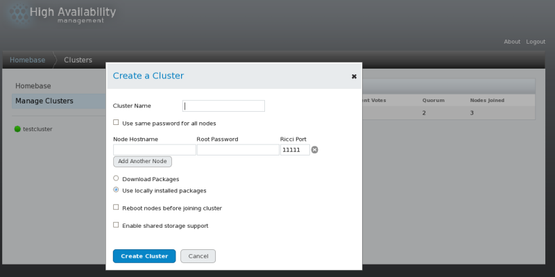
Creating a cluster with luci
consists of naming a cluster, adding cluster nodes to the cluster,
entering their passwords, and submitting the request to create a
cluster. If the node information and passwords are correct, Conga automatically installs software into the cluster nodes and starts the cluster. Create a cluster as follows:
Enter the following parameters on the screen, as necessary:
At the text box, enter a cluster name. The cluster name cannot exceed 15 characters.
If each node in the cluster has the same root password, you can check to autofill the password field as you add nodes.
Enter the node name for a node in the cluster in the column and enter the root password for the node in the column. If you are using a different port for the ricci agent than the default of 11111, you can change that parameter.
Click on and enter the node name and root password for each additional node in the cluster.
If you do not want to upgrade the cluster software packages that
are already installed on the nodes when you create the cluster, leave
the option selected. If you want to upgrade all cluster software packages, select the option.
Whether you select the or the option, if any of the base cluster components are missing (cman, rgmanager, modcluster and all their dependencies), they will be installed. If they cannot be installed, the node creation will fail.
Select
if clustered storage is required; This downloads the packages that
support clustered storage and enables clustered LVM. You should select
this only when you have access to the Resilient Storage Add-On or the
Scalable File System Add-On.
Click Submit. Clicking Submit causes the following actions:
The cluster software packages are downloaded onto the added node.
Cluster software is installed onto the added node (or it is
verified that the appropriate software packages are installed).
The cluster configuration file is updated and propagated to each node in the cluster — including the added node.
The added node joins the cluster.
A message is displayed indicating that the cluster is being
created. Refresh the page to see the current status of the cluster
creation. When the cluster is ready, the display shows the status of the
newly created cluster.
After clicking
Submit to create the cluster, you can still add or delete nodes from the cluster by clicking the or
function from the menu at the top of the cluster node display page. For
information on deleting a node from an existing cluster that is
currently in operation, see
Section 4.2.4, “Deleting a Member from a Cluster”.
3.4. Global Cluster Properties
When you select a cluster to configure, a cluster-specific page is
displayed. The page provides an interface for configuring cluster-wide
properties. You can configure cluster-wide properties by clicking on along the top of the cluster display. This yields a tabbed interface which provides the following tabs: , , , and .
To configure the parameters in those tabs, follow the steps in this
section. If you do not need to configure parameters in a tab, skip the
step for that tab.
tab — This tab displays the cluster name and provides an interface for modifying the configuration version.
The
text box displays the cluster name; it does not accept a cluster name
change. The only way to change the name of a cluster is to create a new
cluster configuration with the new name.
The value is set to 1
by default and is automatically incremented each time you modify your
cluster configuration. However, if you need to set it to another value,
you can specify it at the text box.
If you have changed the value, click Apply for this change to take effect.
tab — This tab provides an interface for configuring these parameters: and .
The values you configure for these parameters are general fencing
properties for the cluster. To configure specific fence devices for the
nodes of the cluster, use the menu item of the cluster display, as described in
Section 3.5, “Configuring Fence Devices”.
The general fencing properties for the cluster you can configure with the tab are summarized as follows:
The parameter is the number of seconds the fence daemon (fenced) waits before fencing a node (a member of the fence domain) after the node has failed. The default value is 0. Its value may be varied to suit cluster and network performance.
The parameter is the number of seconds the fence daemon (fenced) waits before fencing a node after the node joins the fence domain. The default value is 3. A typical setting for is between 20 and 30 seconds, but can vary according to cluster and network performance.
Enter the values required and click Apply for changes to take effect.
For more information about and , refer to the fenced(8) man page.
tab — This tab provides an interface for configuring multicast parameters.
You can use this tab to configure these multicast parameters: and . The default setting is . If you need to use a specific multicast address, click and enter a multicast address into the text box.
You can enter advanced cluster properties by clicking ,
which reveals a list of advanced properties you can reset from their
default values. It is recommended that you leave these properties at
their default values.
Click Apply for changes to take effect.
If you do not specify a multicast address, the Red Hat High
Availability Add-On software creates one based on the cluster ID. It
generates the lower 16 bits of the address and appends them to the upper
portion of the address according to whether the IP protocol is IPV4 or
IPV6:
For IPV4 — The address formed is 239.192. plus the lower 16 bits generated by Red Hat High Availability Add-On software.
For IPV6 — The address formed is FF15:: plus the lower 16 bits generated by Red Hat High Availability Add-On software.
If you do not specify a multicast address, the Red Hat High
Availability Add-On software creates one by generating the lower 16 bits
of the address and appending them to the upper portion of the address,
239.192. To ensure a unique multicast address, the Red Hat High
Availability Add-On software generates the lower 16 bits based on the
cluster ID.
The cluster ID is a unique identifier that cman generates for each cluster. To view the cluster ID, run the cman_tool status command on a cluster node.
If you do specify a multicast address, you should use the 239.192.x.x series (or FF15:: for IPv6) that cman
uses. Otherwise, using a multicast address outside that range may cause
unpredictable results. For example, using 224.0.0.x (which is "All
hosts on the network") may not be routed correctly, or even routed at
all by some hardware.
If you specify a multicast address, make sure that you check the
configuration of routers that cluster packets pass through. Some routers
may take a long time to learn addresses, seriously impacting cluster
performance.
tab — This tab provides an interface for configuring these parameters: , , , , , and . This tab also provides an interface to specify a physical device to use, and to specify the heuristics to use. The parameter is enabled by default.
Table 3.1, “Quorum-Disk Parameters” describes the parameters. If you need to use a quorum disk, click , enter quorum disk parameters, click
Apply, and restart the cluster for the changes to take effect.
Quorum-disk parameters and heuristics depend on the site
environment and the special requirements needed. To understand the use
of quorum-disk parameters and heuristics, refer to the qdisk(5) man page. If you require assistance understanding and using quorum disk, contact an authorized Red Hat support representative.
Table 3.1. Quorum-Disk Parameters
|
Parameter
|
Description
|
|---|
|
|
Disables quorum disk. Disables quorum-disk parameters in the tab.
|
|
|
Enables quorum disk. Enables quorum-disk parameters in the tab.
|
|
|
The frequency of read/write cycles, in seconds. The value of is automatically determined if left blank in the dialog box.
|
|
|
The number of votes the quorum daemon advertises to cman when it has a high enough score. The value of is automatically determined if left blank in the dialog box.
|
|
|
The number of cycles a node must miss to be declared dead. The value of is automatically determined if left blank in the dialog box.
|
|
|
The minimum score for a node to be considered "alive". If omitted or set to 0, the default function, floor((n+1)/2), is used, where n is the sum of the heuristics scores. The value must never exceed the sum of the heuristic scores; otherwise, the quorum disk cannot be available.
|
|
|
Specifies the quorum disk label created by the mkqdisk utility. If this field is used, the quorum daemon reads the /proc/partitions
and checks for qdisk signatures on every block device found, comparing
the label against the specified label. This is useful in configurations
where the quorum device name differs among nodes.
|
|
|
The storage device the quorum daemon uses. The device must be the same on all nodes.
|
|
|
Specifies the quorum disk label created by the mkqdisk utility. If this field contains an entry, the label overrides the field. If this field is used, the quorum daemon reads /proc/partitions
and checks for qdisk signatures on every block device found, comparing
the label against the specified label. This is useful in configurations
where the quorum device name differs among nodes.
|
|
|
— The program used to determine if this heuristic is available. This can be anything that can be executed by /bin/sh -c. A return value of 0 indicates success; anything else indicates failure. This field is required. | | — The frequency (in seconds) at which the heuristic is polled. The default interval for every heuristic is 2 seconds. | | — The weight of this heuristic. Be careful when determining scores for heuristics. The default score for each heuristic is 1. | | — The number of consecutive failures required before this heuristic is declared unavailable. |
|
|
|
Propagates the changes to the cluster configuration file (/etc/cluster/cluster.conf) in each cluster node.
|
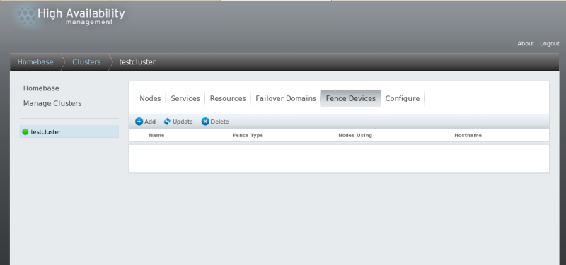
3.5. Configuring Fence Devices
Configuring fence devices consists of creating, updating, and
deleting fence devices for the cluster. You must configure the fence
devices in a cluster before you can configure fencing for the nodes in
the cluster.
Creating a fence device consists of selecting a fence device type and
entering parameters for that fence device (for example, name, IP
address, login, and password). Updating a fence device consists of
selecting an existing fence device and changing parameters for that
fence device. Deleting a fence device consists of selecting an existing
fence device and deleting it.
This section provides procedures for the following tasks:
From the cluster-specific page, you can configure fence devices for that cluster by clicking on
along the top of the cluster display. This displays the fence devices
for the cluster and displays the menu items for fence device
configuration: , , and . This is the starting point of each procedure described in the following sections.
If this is an initial cluster configuration, no fence devices have been created, and therefore none are displayed.
3.5.1. Creating a Fence Device
To create a fence device, follow these steps:
From the configuration page, click . Clicking displays the Add a Fence Instance dialog box. From this drop-down box, select the type of fence device to configure.
Click Submit.
After the fence device has been added, it appears on the configuration page.
3.5.2. Modifying a Fence Device
To modify a fence device, follow these steps:
From the
configuration page, click on the name of the fence device to modify.
This displays the dialog box for that fence device, with the values that
have been configured for the device.
Click Apply and wait for the configuration to be updated.
3.5.3. Deleting a Fence Device
To delete a fence device, follow these steps:
From the configuration page, click the box to the left of the fence device or devices to select the devices to delete.
Click Delete and wait for the configuration to be updated. A message appears indicating which devices are being deleted.
When the configuration has been updated, the deleted fence device no longer appears in the display.
3.6. Configuring Fencing for Cluster Members
Once you have completed the initial steps of creating a cluster and
creating fence devices, you need to configure fencing for the cluster
nodes. To configure fencing for the nodes after creating a new cluster
and configuring the fencing devices for the cluster, follow the steps in
this section. Note that you must configure fencing for each node in the
cluster.
The following sections provide procedures for configuring a single
fence device for a node, configuring a node with a backup fence device,
and configuring a node with redundant power supplies:
3.6.1. Configuring a Single Fence Device for a Node
Use the following procedure to configure a node with a single fence device.
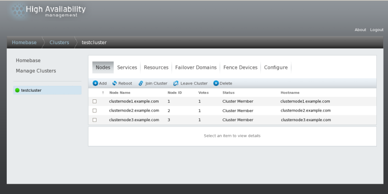
From the cluster-specific page, you can configure fencing for the nodes in the cluster by clicking on
along the top of the cluster display. This displays the nodes that
constitute the cluster. This is also the default page that appears when
you click on the cluster name beneath from the menu on the left side of the luci page.
Click on a node name. Clicking a link for a node causes a page to
be displayed for that link showing how that node is configured.
The node-specific page displays any services that are currently
running on the node, as well as any failover domains of which this node
is a member. You can modify an existing failover domain by clicking on
its name. For information on configuring failover domains, see
Section 3.7, “Configuring a Failover Domain”.
On the node-specific page, click Add a fence method.
Enter a name for the fencing method that you are configuring for this node.
Click Submit. This displays the node-specific screen that now displays the method you have just added under .
Configure a fence instance for this method by clicking
Add a Fence Instance. This displays a drop-down menu from which you can select a fence device you have previously configured, as described in
Section 3.5.1, “Creating a Fence Device”.
Select a fence device for this method. If this fence device
requires that you configure node-specific parameters, the display shows
the parameters to configure. For information on fencing parameters,
refer to
Appendix A, Fence Device Parameters.
Click Submit. This returns you to the node-specific screen with the fence method and fence instance displayed.
3.6.2. Configuring a Backup Fence Device
You can define multiple fencing methods for a node. If fencing fails
using the first method, the system will attempt to fence the node using
the second method.
Use the following procedure to configure a backup fence device for a node.
Beneath the display of the primary method you defined, click Add a fence method.
Enter a name for the backup fencing method that you are configuring for this node and click Submit. This displays the node-specific screen that now displays the method you have just added, below the primary fence method.
Configure a fence instance for this method by clicking
Add a Fence Instance. This displays a drop-down menu from which you can select a fence device you have previously configured, as described in
Section 3.5.1, “Creating a Fence Device”.
Select a fence device for this method. If this fence device
requires that you configure node-specific parameters, the display shows
the parameters to configure. For information on fencing parameters,
refer to
Appendix A, Fence Device Parameters.
Click Submit. This returns you to the node-specific screen with the fence method and fence instance displayed.
You can continue to add fencing methods as needed. You can rearrange
the order of fencing methods that will be used for this node by
clicking on and .
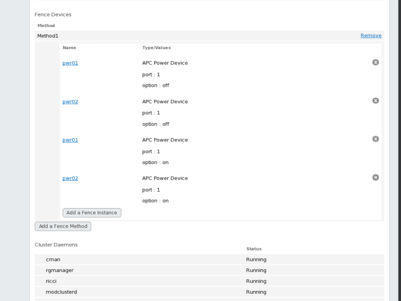
3.6.3. Configuring A Node with Redundant Power
If your cluster is configured with redundant power supplies for your
nodes, you must be sure to configure fencing so that your nodes fully
shut down when they need to be fenced. If you configure each power
supply as a separate fence method, each power supply will be fenced
separately; the second power supply will allow the system to continue
running when the first power supply is fenced and the system will not be
fenced at all. To configure a system with dual power supplies, you must
configure your fence devices so that both power supplies are shut off
and the system is taken completely down. When configuring your system
using Conga, this requires that you configure two instances within a single fencing method.
To configure fencing for a node with dual power supplies, follow the steps in this section.
Before you can configure fencing for a node with redundant power,
you must configure each of the power switches as a fence device for the
cluster. For information on configuring fence devices, see
Section 3.5, “Configuring Fence Devices”.
From the cluster-specific page, click on
along the top of the cluster display. This displays the nodes that
constitute the cluster. This is also the default page that appears when
you click on the cluster name beneath from the menu on the left side of the luci page.
Click on a node name. Clicking a link for a node causes a page to
be displayed for that link showing how that node is configured.
On the node-specific page, click Add a fence method.
Enter a name for the fencing method that you are configuring for this node.
Click Submit. This displays the node-specific screen that now displays the method you have just added under .
Configure the first power supply as a fence instance for this method by clicking
Add a Fence Instance.
This displays a drop-down menu from which you can select one of the
power fencing devices you have previously configured, as described in
Section 3.5.1, “Creating a Fence Device”.
Select one of the power fence devices for this method and enter the appropriate parameters for this device.
Click Submit. This returns you to the node-specific screen with the fence method and fence instance displayed.
Under the same fence method for which you have configured the first power fencing device, click
Add a Fence Instance.
This displays a drop-down menu from which you can select the second
power fencing devices you have previously configured, as described in
Section 3.5.1, “Creating a Fence Device”.
Select the second of the power fence devices for this method and enter the appropriate parameters for this device.
Click
Submit. This
returns you to the node-specific screen with the fence methods and
fence instances displayed, showing that each device will power the
system off in sequence and power the system on in sequence. This is
shown in
Figure 3.6, “Dual-Power Fencing Configuration”.
3.7. Configuring a Failover Domain
A failover domain is a named subset of cluster nodes that are
eligible to run a cluster service in the event of a node failure. A
failover domain can have the following characteristics:
Unrestricted — Allows you to specify that a subset of members are
preferred, but that a cluster service assigned to this domain can run on
any available member.
Restricted — Allows you to restrict the members that can run a
particular cluster service. If none of the members in a restricted
failover domain are available, the cluster service cannot be started
(either manually or by the cluster software).
Unordered — When a cluster service is assigned to an unordered
failover domain, the member on which the cluster service runs is chosen
from the available failover domain members with no priority ordering.
Ordered — Allows you to specify a preference order among the
members of a failover domain. The member at the top of the list is the
most preferred, followed by the second member in the list, and so on.
Failback — Allows you to specify whether a service in the failover
domain should fail back to the node that it was originally running on
before that node failed. Configuring this characteristic is useful in
circumstances where a node repeatedly fails and is part of an ordered
failover domain. In that circumstance, if a node is the preferred node
in a failover domain, it is possible for a service to fail over and fail
back repeatedly between the preferred node and another node, causing
severe impact on performance.
The failback characteristic is applicable only if ordered failover is configured.
Changing a failover domain configuration has no effect on currently running services.
Failover domains are not required for operation.
By default, failover domains are unrestricted and unordered.
In a cluster with several members, using a restricted failover domain
can minimize the work to set up the cluster to run a cluster service
(such as httpd), which requires you to set
up the configuration identically on all members that run the cluster
service). Instead of setting up the entire cluster to run the cluster
service, you must set up only the members in the restricted failover
domain that you associate with the cluster service.
To configure a preferred member, you can create an unrestricted
failover domain comprising only one cluster member. Doing that causes a
cluster service to run on that cluster member primarily (the preferred
member), but allows the cluster service to fail over to any of the other
members.
The following sections describe adding, modifying, and deleting a failover domain:
3.7.1. Adding a Failover Domain
To add a failover domain, follow the steps in this section.
From the cluster-specific page, you can configure Failover Domains for that cluster by clicking on along the top of the cluster display. This displays the failover domains that have been configured for this cluster.
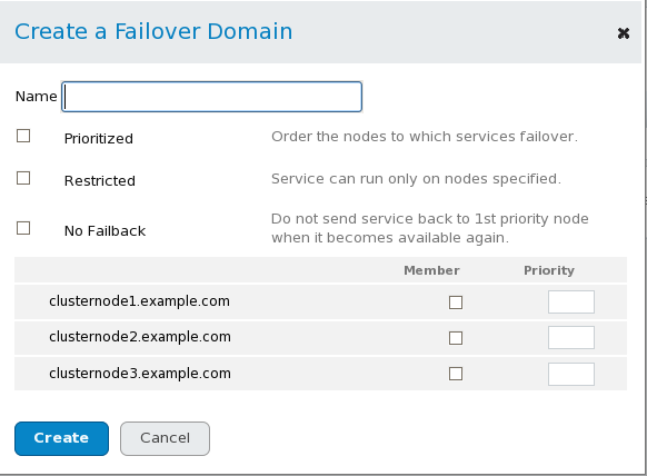
In the Create a Failover Domain window, specify a failover domain name at the text box.
The name should be descriptive enough to distinguish its purpose relative to other names used in your cluster.
To enable setting failover priority of the members in the failover domain, click the checkbox. With checked, you can set the priority value, , for each node selected as members of the failover domain.
To restrict failover to members in this failover domain, click the checkbox. With checked, services assigned to this failover domain fail over only to nodes in this failover domain.
To specify that a node does not fail back in this failover domain, click the checkbox. With
checked, if a service fails over from a preferred node, the service
does not fail back to the original node once it has recovered.
Configure members for this failover domain. Click the checkbox for each node that is to be a member of the failover domain. If is checked, set the priority in the text box for each member of the failover domain.
Click Create. This displays the Failover Domains
page with the newly-created failover domain displayed. A message
indicates that the new domain is being created. Refresh the page for an
updated status.
3.7.2. Modifying a Failover Domain
To modify a failover domain, follow the steps in this section.
From the cluster-specific page, you can configure Failover Domains for that cluster by clicking on along the top of the cluster display. This displays the failover domains that have been configured for this cluster.
Click on the name of a failover domain. This displays the configuration page for that failover domain.
To modify the , , or properties for the failover domain, click or unclick the checkbox next to the property and click Update Properties.
To modify the failover domain membership, click or unclick the
checkbox next to the cluster member. If the failover domain is
prioritized, you can also modify the priority setting for the cluster
member. Click Update Settings.
3.7.3. Deleting a Failover Domain
To delete a failover domain, follow the steps in this section.
From the cluster-specific page, you can configure Failover Domains for that cluster by clicking on along the top of the cluster display. This displays the failover domains that have been configured for this cluster.
Select the checkbox for the failover domain to delete.
Click on .
3.8. Configuring Global Cluster Resources
You can configure global resources that can be used by any service
running in the cluster, and you can configure resources that are
available only to a specific service.
From the cluster-specific page, you can add resources to that cluster by clicking on along the top of the cluster display. This displays the resources that have been configured for that cluster.
Click . This displays the drop-down menu.
Click the drop-down box under and select the type of resource to configure.
Click Submit. Clicking Submit returns to the resources page that displays the display of Resources, which displays the added resource (and other resources).
To modify an existing resource, perform the following steps.
From the luci page, click on the name of the resource to modify. This displays the parameters for that resource.
Edit the resource parameters.
Click Apply.
To delete an existing resource, perform the following steps.
From the luci page, click the checkbox for any resources to delete.
Click .
3.9. Adding a Cluster Service to the Cluster
To add a cluster service to the cluster, follow the steps in this section.
From the cluster-specific page, you can add services to that cluster by clicking on along the top of the cluster display. This displays the services that have been configured for that cluster. (From the page, you can also start, restart, and disable a service, as described in
Section 4.4, “Managing High-Availability Services”.)
Click . This displays the window.
On the Add a Service window, at the text box, type the name of the service.
Use a descriptive name that clearly distinguishes the service from other services in the cluster.
Check the checkbox if you want the service to start automatically when a cluster is started and running. If the checkbox is not checked, the service must be started manually any time the cluster comes up from the stopped state.
Check the checkbox to set a policy wherein the service only runs on nodes that have no other services running on them.
If you have configured failover domains for the cluster, you can use the dropdown menu of the parameter to select a failover domain for this service. For information on configuring failover domains, see
Section 3.7, “Configuring a Failover Domain”.
Use the drop-down box to select a recovery policy for the service. The options are to relocate, restart, or disable the service.
If you select
as the recovery policy for the service, you can specify the maximum
number of restart failures before relocating and the length of time in
seconds after which to forget a restart.
To add a resource to the service, click Add a resource. Clicking Add a resource
causes the display of a drop-down box that allows you to add an
existing Global resource or to add a new resource that is available only to this service.
To add an existing Global resource, click on the name of the existing resource from the
Add a resource to this service drop-down box. This displays the resource and its parameters on the
page for the service you are configuring. You cannot edit the
parameters of a Global resource from this screen. For information on
adding or modifying Global resources, see
Section 3.8, “Configuring Global Cluster Resources”).
To add a new resource that is available only to this service, select the type of resource to configure from the
Add a resource drop-down box and enter the resource parameters for the resource you are adding.
Appendix B, HA Resource Parameters describes resource parameters.
If you are adding a Samba-service resource, connect a Samba-service resource directly to the service, not to a resource within a service.
If you want to add child resources to the resource you are defining, click Add a child resource. Clicking Add a child resource causes the display of the
drop-down box, from which you can add an existing Global resource or
add a new resource that is available only to this service. You can
continue adding children resources to the resource to suit your
requirements.
When you have completed adding resources to the service, and have completed adding children resources to resources, click Submit. Clicking Submit returns to the page displaying the added service (and other services).
To verify the existence of the IP service resource used in a cluster service, you must use the /sbin/ip addr list command on a cluster node. The following output shows the /sbin/ip addr list command executed on a node running a cluster service:
1: lo: <LOOPBACK,UP> mtu 16436 qdisc noqueue
    link/loopback 00:00:00:00:00:00 brd 00:00:00:00:00:00
    inet 127.0.0.1/8 scope host lo
    inet6 ::1/128 scope host
       valid_lft forever preferred_lft forever
2: eth0: <BROADCAST,MULTICAST,UP> mtu 1356 qdisc pfifo_fast qlen 1000
    link/ether 00:05:5d:9a:d8:91 brd ff:ff:ff:ff:ff:ff
    inet 10.11.4.31/22 brd 10.11.7.255 scope global eth0
    inet6 fe80::205:5dff:fe9a:d891/64 scope link
    inet 10.11.4.240/22 scope global secondary eth0
       valid_lft forever preferred_lft forever
To modify an existing service, perform the following steps.
From the luci
page, click on the name of the service to modify. This displays the
parameters and resources that have been configured for that service.
Edit the service parameters.
Click Submit.
To delete an existing resource, perform the following steps.
From the luci page, click the checkbox for any services to delete.
Click .
Chapter 4. Managing Red Hat High Availability Add-On With Conga
This chapter describes various administrative tasks for managing Red
Hat High Availability Add-On and consists of the following sections:
4.1. Adding an Existing Cluster to the luci Interface
If you have previously created a High Availability Add-On cluster you can easily add the cluster to the luci interface so that you can manage the cluster with Conga.
To add an existing cluster to the luci interface, follow these steps:
Click from the menu on the left side of the luci page. The screen appears.
Click . The screen appears.
Enter the node hostname and root password of any of the nodes in
the existing cluster. Since each node in the cluster contains all of the
configuration information for the cluster, this should provide enough
information to add the cluster to the luci interface.
Click Connect. The screen then displays the cluster name and the remaining nodes in the cluster.
Enter the individual passwords for each node in the cluster, or enter one password and select .
Click Add Cluster. The previously-configured cluster now displays on the screen.
4.2. Managing Cluster Nodes
This section documents how to perform the following node-management functions through the luci server component of Conga:
4.2.1. Rebooting a Cluster Node
To reboot a node in a cluster, perform the following steps:
From the cluster-specific page, click on
along the top of the cluster display. This displays the nodes that
constitute the cluster. This is also the default page that appears when
you click on the cluster name beneath from the menu on the left side of the luci page.
Select the node to reboot by clicking the checkbox for that node.
Select the
function from the menu at the top of the page. This causes the selected
node to reboot and a message appears at the top of the page indicating
that the node is being rebooted.
Refresh the page to see the updated status of the node.
It is also possible to reboot more than one node at a time by selecting all of the nodes to reboot before clicking on .
4.2.2. Causing a Node to Leave or Join a Cluster
You can use the luci server component of Conga to cause a node to leave an active cluster by stopping all cluster services on the node. You can also use the luci server component of Conga to cause a node that has left a cluster to rejoin the cluster.
Causing a node to leave a cluster does not remove the cluster
configuration information from that node, and the node still appears in
the cluster node display with a status of
Not a cluster member. For information on deleting the node entirely from the cluster configuration, see
Section 4.2.4, “Deleting a Member from a Cluster”.
To cause a node to leave a cluster, perform the following steps.
This shuts down the cluster software in the node. Making a node leave a
cluster prevents the node from automatically joining the cluster when it
is rebooted.
From the cluster-specific page, click on
along the top of the cluster display. This displays the nodes that
constitute the cluster. This is also the default page that appears when
you click on the cluster name beneath from the menu on the left side of the luci page.
Select the node you want to leave the cluster by clicking the checkbox for that node.
Select the
function from the menu at the top of the page. This causes a message to
appear at the top of the page indicating that the node is being
stopped.
Refresh the page to see the updated status of the node.
It is also possible to cause more than one node at a time to leave
the cluster by selecting all of the nodes to leave the cluster before
clicking on .
To cause a node to rejoin a cluster, select any nodes you want to
have rejoin the cluster by clicking the checkbox for those nodes and
selecting . This makes the selected nodes join the cluster, and allows the selected nodes to join the cluster when they are rebooted.
4.2.3. Adding a Member to a Running Cluster
To add a member to a running cluster, follow the steps in this section.
From the cluster-specific page, click
along the top of the cluster display. This displays the nodes that
constitute the cluster. This is also the default page that appears when
you click on the cluster name beneath from the menu on the left side of the luci page.
Click . Clicking causes the display of the Add nodes to this cluster window.
Enter the node name in the text box; enter the root password in the text box. Check the checkbox if clustered storage is required. If you want to add more nodes, click Add Another Node and enter the node name and password for the each additional node.
Click Add Nodes. Clicking Add Nodes causes the following actions:
The cluster software packages are downloaded onto the added node.
Cluster software is installed onto the added node (or it is
verified that the appropriate software packages are installed)
The cluster configuration file is updated and propagated to each node in the cluster — including the added node.
The added node joins the cluster.
The page appears with a message indicating that the node is being added to the cluster. Refresh the page to update the status.
4.2.4. Deleting a Member from a Cluster
To delete a member from an existing cluster that is currently in operation, follow the steps in this section.
From the cluster-specific page, click
along the top of the cluster display. This displays the nodes that
constitute the cluster. This is also the default page that appears when
you click on the cluster name beneath from the menu on the left side of the luci page.
To allow services running on a node to fail over when the node is deleted, skip the next step.
Select the node or nodes to delete.
Click . The Nodes page indicates that the node is being removed. Refresh the page to see the current status.
4.3. Starting, Stopping, Restarting, and Deleting Clusters
You can start, stop, and restart a cluster by performing these
actions on the individual nodes in the cluster. From the
cluster-specific page, click on along the top of the cluster display. This displays the nodes that constitute the cluster.
To stop a cluster, perform the following steps. This shuts down the
cluster software in the nodes, but does not remove the cluster
configuration information from the nodes and the nodes still appear in
the cluster node display with a status of Not a cluster member.
Select all of the nodes in the cluster by clicking on the checkbox next to each node.
Select the
function from the menu at the top of the page. This causes a message to
appear at the top of the page indicating that each node is being
stopped.
Refresh the page to see the updated status of the nodes.
To start a cluster, perform the following steps:
Select all of the nodes in the cluster by clicking on the checkbox next to each node.
Select the function from the menu at the top of the page.
Refresh the page to see the updated status of the nodes.
To restart a running cluster, first stop all of the nodes in cluster,
then start all of the nodes in the cluster, as described above.
To delete a cluster entirely from the luci interface, perform the following steps:
Select all of the nodes in the cluster by clicking on the checkbox next to each node.
Select the
function from the menu at the top of the page. This removes the cluster
configuration information from the nodes and removes them from the
cluster display.
Click on on the left side of the screen to display the existing clusters.
Select the cluster to delete and click .
4.4. Managing High-Availability Services
Start a service.
Restart a service.
Disable a service
Delete a service
Relocate a service
From the cluster-specific page, you can manage services for that cluster by clicking on along the top of the cluster display. This displays the services that have been configured for that cluster.
Starting a service — To start any services that are not currently
running, select any services you want to start by clicking the checkbox
for that service and clicking .
You can also start an individual service by clicking on the name of the service on the
page. This displays the service configuration page. At the top right
corner of the service configuration page are the same icons for , , , and . Clicking on the icon starts the service you have displayed.
Restarting a service — To restart any services that are currently
running. select any services you want to restart by clicking the
checkbox for that service and clicking .
You can also restart an individual service by clicking on the name of the service on the
page. This displays the service configuration page. At the top right
corner of the service configuration page are the same icons for , , , and . Clicking on the icon starts the service you have displayed.
—
To disable any service that is currently running, select any services
you want to disable by clicking the checkbox for that service and
clicking .
You can also disable an individual service by clicking on the name of the service on the
page. This displays the service configuration page. At the top right
corner of the service configuration page are the same icons for , , , and . Clicking on the icon starts the service you have displayed.
—
To delete any services that are not currently running, select any
services you want to disable by clicking the checkbox for that service
and clicking .
You can also delete an individual service by clicking on the name of the service on the
page. This displays the service configuration page. At the top right
corner of the service configuration page are the same icons for , , , and . Clicking on the icon starts the service you have displayed.
—
To relocate a running service, click on the name of the service in the
services display. This causes the services configuration page for the
service to be displayed, with a display indicating on which node the
service is currently running.
From the Start on node... drop-down box, select the node on which you want to relocate the service, and click on the
icon. A message appears at the top of the screen indicating that the
service is being started. You may need to refresh the screen to see the
new display indicating that the service is running on the node you have
selected.
4.5. Diagnosing and Correcting Problems in a Cluster
For information about diagnosing and correcting problems in a cluster, contact an authorized Red Hat support representative.
Chapter 5. Configuring Red Hat High Availability Add-On With Command Line Tools
This chapter describes how to configure Red Hat High Availability
Add-On software by directly editing the cluster configuration file (/etc/cluster/cluster.conf)
and using command-line tools. The chapter provides procedures about
building a configuration file one section at a time, starting with a
sample file provided in the chapter. As an alternative to starting with a
sample file provided here, you could copy a skeleton configuration file
from the cluster.conf man page. However,
doing so would not necessarily align with information provided in
subsequent procedures in this chapter. There are other ways to create
and configure a cluster configuration file; this chapter provides
procedures about building a configuration file one section at a time.
Also, keep in mind that this is just a starting point for developing a
configuration file to suit your clustering needs.
This chapter consists of the following sections:
Make sure that your deployment of High Availability Add-On meets your
needs and can be supported. Consult with an authorized Red Hat
representative to verify your configuration prior to deployment. In
addition, allow time for a configuration burn-in period to test failure
modes.
This chapter references commonly used cluster.conf elements and attributes. For a comprehensive list and description of cluster.conf elements and attributes, refer to the cluster schema at /usr/share/cluster/cluster.rng, and the annotated schema at /usr/share/doc/cman-X.Y.ZZ/cluster_conf.html (for example /usr/share/doc/cman-3.0.12/cluster_conf.html).
Certain procedure in this chapter call for using the cman_tool -r command to propagate a cluster configuration throughout a cluster. Using that command requires that ricci is running.
Procedures in this chapter, may include specific commands for some of the command-line tools listed in
Appendix D, Command Line Tools Summary. For more information about all commands and variables, refer to the man page for each command-line tool.
Configuring Red Hat High Availability Add-On software with command-line tools consists of the following steps:
5.2. Creating a Basic Cluster Configuration File
Provided that cluster hardware, Red Hat Enterprise Linux, and High
Availability Add-On software are installed, you can create a cluster
configuration file (/etc/cluster/cluster.conf)
and start running the High Availability Add-On. As a starting point
only, this section describes how to create a skeleton cluster
configuration file without fencing, failover domains, and HA services.
Subsequent sections describe how to configure those parts of the
configuration file.
This is just an interim step to create a cluster configuration file;
the resultant file does not have any fencing and is not considered to
be a supported configuration.
The following steps describe how to create and configure a skeleton
cluster configuration file. Ultimately, the configuration file for your
cluster will vary according to the number of nodes, the type of fencing,
the type and number of HA services, and other site-specific
requirements.
(Optional) If you
are configuring a two-node cluster, you can add the following line to
the configuration file to allow a single node to maintain quorum (for
example, if one node fails):
<cman two_node="1" expected_votes="1"/>
In the clusternodes section, specify the node name and the node ID of each node using the clusternode attributes: name and nodeid.
Save /etc/cluster/cluster.conf.
Validate the file with against the cluster schema (cluster.rng) by running the ccs_config_validate command. For example:
[root@example-01 ~]# ccs_config_validate
Configuration validates
Propagate the configuration file to /etc/cluster/ in each cluster node. For example, you could propagate the file to other cluster nodes using the scp command.
Propagating the cluster configuration file this way is necessary
the first time a cluster is created. Once a cluster is installed and
running, the cluster configuration file can be propagated using the cman_tool version -r. It is possible to use the scp command to propagate an updated configuration file; however, the cluster software must be stopped on all nodes while using the scp command.In addition, you should run the ccs_config_validate if you propagate an updated configuration file via the scp.
While there are other elements and attributes present in the sample configuration file (for example, fence and fencedevices,
there is no need to populate them now. Subsequent procedures in this
chapter provide information about specifying other elements and
attributes.
Start the cluster. At each cluster node run the following command:
service cman start
For example:
[root@example-01 ~]# service cman start
Starting cluster:
   Checking Network Manager...                             [  OK  ]
   Global setup...                                         [  OK  ]
   Loading kernel modules...                               [  OK  ]
   Mounting configfs...                                    [  OK  ]
   Starting cman...                                        [  OK  ]
   Waiting for quorum...                                   [  OK  ]
   Starting fenced...                                      [  OK  ]
   Starting dlm_controld...                                [  OK  ]
   Starting gfs_controld...                                [  OK  ]
   Unfencing self...                                       [  OK  ]
   Joining fence domain...                                 [  OK  ]
At any cluster node, run cman_tools nodes to verify that the nodes are functioning as members in the cluster (signified as "M" in the status column, "Sts"). For example:
[root@example-01 ~]# cman_tool nodes
Node  Sts   Inc   Joined               Name
   1   M    548   2010-09-28 10:52:21  node-01.example.com
   2   M    548   2010-09-28 10:52:21  node-02.example.com
   3   M    544   2010-09-28 10:52:21  node-03.example.com
Basic Configuration Examples
Example 5.1. cluster.conf Sample: Basic Configuration
<cluster name="mycluster" config_version="2">
   <clusternodes>
     <clusternode name="node-01.example.com" nodeid="1">
         <fence>
         </fence>
     </clusternode>
     <clusternode name="node-02.example.com" nodeid="2">
         <fence>
         </fence>
     </clusternode>
     <clusternode name="node-03.example.com" nodeid="3">
         <fence>
         </fence>
     </clusternode>
   </clusternodes>
   <fencedevices>
   </fencedevices>
   <rm>
   </rm>
</cluster>
Example 5.2. cluster.conf Sample: Basic Two-Node Configuration
<cluster name="mycluster" config_version="2">
   <cman two_node="1" expected_votes="1"/>
   <clusternodes>
     <clusternode name="node-01.example.com" nodeid="1">
         <fence>
         </fence>
     </clusternode>
     <clusternode name="node-02.example.com" nodeid="2">
         <fence>
         </fence>
     </clusternode>
   </clusternodes>
   <fencedevices>
   </fencedevices>
   <rm>
   </rm>
</cluster>
Configuring fencing consists of (a) specifying one or more fence
devices in a cluster and (b) specifying one or more fence methods for
each node (using a fence device or fence devices specified).
Based on the type of fence devices and fence methods required for your configuration, configure cluster.conf as follows:
At the
clusternodes section, within the
fence element of each
clusternode section, specify each fence method of the node. Specify the fence method name, using the
method attribute,
name. Specify the fence device for each fence method, using the
device element and its attributes,
name and fence-device-specific parameters.
Example 5.4, “Fence Methods Added to cluster.conf ” shows an example of a fence method with one fence device for each node in the cluster.
For non-power fence methods (that is, SAN/storage fencing), at the clusternodes section, add an unfence section. The unfence section does not contain method sections like the fence section does. It contains device references directly, which mirror the corresponding device sections for fence, with the notable addition of the explicit action (action) of "on" or "enable". The same fencedevice is referenced by both fence and unfence device lines, and the same per-node arguments should be repeated.
For more information about unfence refer to the fence_node man page.
Update the config_version attribute by incrementing its value (for example, changing from config_version="2" to config_version="3">).
Save /etc/cluster/cluster.conf.
(Optional) Validate the updated file against the cluster schema (cluster.rng) by running the ccs_config_validate command. For example:
[root@example-01 ~]# ccs_config_validate
Configuration validates
Run the cman_tool version -r command to propagate the configuration to the rest of the cluster nodes.
Verify that the updated configuration file has been propagated.
If required, you can configure complex configurations with multiple
fence methods per node and with multiple fence devices per fence method.
When specifying multiple fence methods per node, if fencing fails using
the first method, fenced, the fence daemon, tries the next method, and continues to cycle through methods until one succeeds.
Sometimes, fencing a node requires disabling two I/O paths or two
power ports. This is done by specifying two or more devices within a
fence method. fenced runs the fence agent once for each fence-device line; all must succeed for fencing to be considered successful.
You can find more information about configuring specific fence
devices from a fence-device agent man page (for example, the man page
for
fence_apc). In addition, you can get more information about fencing parameters from
Appendix A, Fence Device Parameters, the fence agents in
/usr/sbin/, the cluster schema at
/usr/share/cluster/cluster.rng, and the annotated schema at
/usr/share/doc/cman-X.Y.ZZ/cluster_conf.html (for example,
/usr/share/doc/cman-3.0.12/cluster_conf.html).
Fencing Configuration Examples
The following examples show a simple configuration with one fence method per node and one fence device per fence method:
The following examples show more complex configurations:
The examples in this section are not exhaustive; that is, there may
be other ways to configure fencing depending on your requirements.
Example 5.3. APC Fence Device Added to cluster.conf
<cluster name="mycluster" config_version="3">
   <clusternodes>
     <clusternode name="node-01.example.com" nodeid="1">
         <fence>
         </fence>
     </clusternode>
     <clusternode name="node-02.example.com" nodeid="2">
         <fence>
         </fence>
     </clusternode>
     <clusternode name="node-03.example.com" nodeid="3">
         <fence>
         </fence>
     </clusternode>
   </clusternodes>
   <fencedevices>
         <fencedevice agent="fence_apc" ipaddr="apc_ip_example" login="login_example" name="apc" passwd="password_example"/>
   </fencedevices>
   <rm>
   </rm>
</cluster>
In this example, a fence device (fencedevice) has been added to the fencedevices element, specifying the fence agent (agent) as fence_apc, the IP address (ipaddr) as apc_ip_example, the login (login) as login_example, the name of the fence device (name) as apc, and the password (passwd) as password_example.
Example 5.4. Fence Methods Added to cluster.conf
<cluster name="mycluster" config_version="3">
   <clusternodes>
     <clusternode name="node-01.example.com" nodeid="1">
         <fence>
            <method name="APC">
              <device name="apc" port="1"/>
             </method>
         </fence>
     </clusternode>
     <clusternode name="node-02.example.com" nodeid="2">
         <fence>
            <method name="APC">
              <device name="apc" port="2"/>
            </method>
         </fence>
     </clusternode>
     <clusternode name="node-03.example.com" nodeid="3">
         <fence>
            <method name="APC">
              <device name="apc" port="3"/>
            </method>
         </fence>
     </clusternode>
   </clusternodes>
   <fencedevices>
         <fencedevice agent="fence_apc" ipaddr="apc_ip_example" login="login_example" name="apc" passwd="password_example"/>
   </fencedevices>
   <rm>
   </rm>
</cluster>
In this example, a fence method (method) has been added to each node. The name of the fence method (name) for each node is APC. The device (device) for the fence method in each node specifies the name (name) as apc and a unique APC switch power port number (port) for each node. For example, the port number for node-01.example.com is 1 (port="1"). The device name for each node (device name="apc") points to the fence device by the name (name) of apc in this line of the fencedevices element: fencedevice agent="fence_apc" ipaddr="apc_ip_example" login="login_example" name="apc" passwd="password_example"/.
Example 5.5. cluster.conf: Multiple Fence Methods per Node
<cluster name="mycluster" config_version="3">
   <clusternodes>
     <clusternode name="node-01.example.com" nodeid="1">
         <fence>
            <method name="APC">
              <device name="apc" port="1"/>
             </method>
            <method name="SAN">
	      <device name="sanswitch1" port="11"/>
             </method>
         </fence>
         <unfence>
             <device name="sanswitch1" port="11" action="on"/>
         </unfence
     </clusternode>
     <clusternode name="node-02.example.com" nodeid="2">
         <fence>
            <method name="APC">
              <device name="apc" port="2"/>
            </method>
            <method name="SAN">
	      <device name="sanswitch1" port="12"/>
             </method>
         </fence>
         <unfence>
             <device name="sanswitch1" port="12" action="on"/>
         </unfence
     </clusternode>
     <clusternode name="node-03.example.com" nodeid="3">
         <fence>
            <method name="APC">
              <device name="apc" port="3"/>
            </method>
            <method name="SAN">
	      <device name="sanswitch1" port="13"/>
             </method>
         </fence>
         <unfence>
             <device name="sanswitch1" port="13" action="on"/>
         </unfence
     </clusternode>
   </clusternodes>
   <fencedevices>
        <fencedevice agent="fence_apc" ipaddr="apc_ip_example" login="login_example" name="apc" passwd="password_example"/>
        <fencedevice agent="fence_sanbox2" ipaddr="san_ip_example"
login="login_example" name="sanswitch1 passwd="password_example"
   </fencedevices>
   <rm>
   </rm>
</cluster>
Example 5.6. cluster.conf: Fencing, Multipath Multiple Ports
<cluster name="mycluster" config_version="3">
   <clusternodes>
     <clusternode name="node-01.example.com" nodeid="1">
         <fence>
            <method name="SAN-multi">
	      <device name="sanswitch1" port="11"/>
	      <device name="sanswitch2" port="11"/>
	    </method>
         </fence>
         <unfence>
             <device name="sanswitch1" port="11" action="on"/>
             <device name="sanswitch2" port="11" action="on"/>
         </unfence
     </clusternode>
     <clusternode name="node-02.example.com" nodeid="2">
         <fence>
            <method name="SAN-multi">
	      <device name="sanswitch1" port="12"/>
	      <device name="sanswitch2" port="12"/>
            </method>
         </fence>
         <unfence>
             <device name="sanswitch1" port="12" action="on"/>
             <device name="sanswitch2" port="12" action="on"/>
         </unfence
     </clusternode>
     <clusternode name="node-03.example.com" nodeid="3">
         <fence>
            <method name="SAN-multi">
	      <device name="sanswitch1" port="13"/>
	      <device name="sanswitch2" port="13"/>
            </method>
         </fence>
         <unfence>
             <device name="sanswitch1" port="13" action="on"/>
             <device name="sanswitch2" port="13" action="on"/>
         </unfence
     </clusternode>
   </clusternodes>
   <fencedevices>
        <fencedevice agent="fence_sanbox2" ipaddr="san_ip_example"
login="login_example" name="sanswitch1 passwd="password_example" "
        <fencedevice agent="fence_sanbox2" ipaddr="san_ip_example"
login="login_example" name="sanswitch2 passwd="password_example"
   </fencedevices>
   <rm>
   </rm>
</cluster>
Example 5.7. cluster.conf: Fencing Nodes with Dual Power Supplies
<cluster name="mycluster" config_version="3">
   <clusternodes>
     <clusternode name="node-01.example.com" nodeid="1">
         <fence>
            <method name="APC-dual">
              <device name="apc1" port="1"action="off"/>
              <device name="apc2" port="1"action="off"/>
              <device name="apc1" port="1"action="on"/>
              <device name="apc2" port="1"action="on"/>
             </method>
         </fence>
     </clusternode>
     <clusternode name="node-02.example.com" nodeid="2">
         <fence>
            <method name="APC-dual">
              <device name="apc1" port="2"action="off"/>
              <device name="apc2" port="2"action="off"/>
              <device name="apc1" port="2"action="on"/>
              <device name="apc2" port="2"action="on"/>
            </method>
         </fence>
     </clusternode>
     <clusternode name="node-03.example.com" nodeid="3">
         <fence>
            <method name="APC-dual">
              <device name="apc1" port="3"action="off"/>
              <device name="apc2" port="3"action="off"/>
              <device name="apc1" port="3"action="on"/>
              <device name="apc2" port="3"action="on"/>
            </method>
         </fence>
     </clusternode>
   </clusternodes>
   <fencedevices>
       <fencedevice agent="fence_apc" ipaddr="apc_ip_example" login="login_example" name="apc1" passwd="password_example"/>
       <fencedevice agent="fence_apc" ipaddr="apc_ip_example" login="login_example" name="apc2" passwd="password_example"/>
   </fencedevices>
   <rm>
   </rm>
</cluster>
When using power switches to fence nodes with dual power supplies,
the agents must be told to turn off both power ports before restoring
power to either port. The default off-on behavior of the agent could
result in the power never being fully disabled to the node.
5.4. Configuring Failover Domains
A failover domain is a named subset of cluster nodes that are
eligible to run a cluster service in the event of a node failure. A
failover domain can have the following characteristics:
Unrestricted — Allows you to specify that a subset of members are
preferred, but that a cluster service assigned to this domain can run on
any available member.
Restricted — Allows you to restrict the members that can run a
particular cluster service. If none of the members in a restricted
failover domain are available, the cluster service cannot be started
(either manually or by the cluster software).
Unordered — When a cluster service is assigned to an unordered
failover domain, the member on which the cluster service runs is chosen
from the available failover domain members with no priority ordering.
Ordered — Allows you to specify a preference order among the
members of a failover domain. Ordered failover domains select the node
with the lowest priority number first. That is, the node in a failover
domain with a priority number of "1" specifies the highest priority, and
therefore is the most preferred node in a failover domain. After that
node, the next preferred node would be the node with the next highest
priority number, and so on.
Failback — Allows you to specify whether a service in the failover
domain should fail back to the node that it was originally running on
before that node failed. Configuring this characteristic is useful in
circumstances where a node repeatedly fails and is part of an ordered
failover domain. In that circumstance, if a node is the preferred node
in a failover domain, it is possible for a service to fail over and fail
back repeatedly between the preferred node and another node, causing
severe impact on performance.
The failback characteristic is applicable only if ordered failover is configured.
Changing a failover domain configuration has no effect on currently running services.
Failover domains are not required for operation.
By default, failover domains are unrestricted and unordered.
In a cluster with several members, using a restricted failover domain
can minimize the work to set up the cluster to run a cluster service
(such as httpd), which requires you to set
up the configuration identically on all members that run the cluster
service). Instead of setting up the entire cluster to run the cluster
service, you must set up only the members in the restricted failover
domain that you associate with the cluster service.
To configure a preferred member, you can create an unrestricted
failover domain comprising only one cluster member. Doing that causes a
cluster service to run on that cluster member primarily (the preferred
member), but allows the cluster service to fail over to any of the other
members.
To configure a failover domain, use the following procedures:
Open /etc/cluster/cluster.conf at any node in the cluster.
Add the following skeleton section within the rm element for each failover domain to be used:
        <failoverdomains>
            <failoverdomain name="" nofailback="" ordered="" restricted="">
                <failoverdomainnode name="" priority=""/>
                <failoverdomainnode name="" priority=""/>
                <failoverdomainnode name="" priority=""/>
            </failoverdomain>
        </failoverdomains>
The number of failoverdomainnode attributes depends on the number of nodes in the failover domain. The skeleton failoverdomain section in preceding text shows three failoverdomainnode elements (with no node names specified), signifying that there are three nodes in the failover domain.
In the
failoverdomain section, provide the values for the elements and attributes. For descriptions of the elements and attributes, refer to the
failoverdomain section of the annotated cluster schema. The annotated cluster schema is available at
/usr/share/doc/cman-X.Y.ZZ/cluster_conf.html (for example
/usr/share/doc/cman-3.0.12/cluster_conf.html) in any of the cluster nodes. For an example of a
failoverdomains section, refer to
Example 5.8, “A Failover Domain Added to cluster.conf ”.
Update the config_version attribute by incrementing its value (for example, changing from config_version="2" to config_version="3">).
Save /etc/cluster/cluster.conf.
(Optional) Validate the file with against the cluster schema (cluster.rng) by running the ccs_config_validate command. For example:
[root@example-01 ~]# ccs_config_validate
Configuration validates
Run the cman_tool version -r command to propagate the configuration to the rest of the cluster nodes.
Example 5.8. A Failover Domain Added to cluster.conf
<cluster name="mycluster" config_version="3">
   <clusternodes>
     <clusternode name="node-01.example.com" nodeid="1">
         <fence>
            <method name="APC">
              <device name="apc" port="1"/>
             </method>
         </fence>
     </clusternode>
     <clusternode name="node-02.example.com" nodeid="2">
         <fence>
            <method name="APC">
              <device name="apc" port="2"/>
            </method>
         </fence>
     </clusternode>
     <clusternode name="node-03.example.com" nodeid="3">
         <fence>
            <method name="APC">
              <device name="apc" port="3"/>
            </method>
         </fence>
     </clusternode>
   </clusternodes>
   <fencedevices>
         <fencedevice agent="fence_apc" ipaddr="apc_ip_example" login="login_example" name="apc" passwd="password_example"/>
   </fencedevices>
   <rm>
       <failoverdomains>
           <failoverdomain name="example_pri" nofailback="0" ordered="1" restricted="0">
               <failoverdomainnode name="node-01.example.com" priority="1"/>
               <failoverdomainnode name="node-02.example.com" priority="2"/>
               <failoverdomainnode name="node-03.example.com" priority="3"/>
           </failoverdomain>
       </failoverdomains>
   </rm>
</cluster>
The failoverdomains section contains a failoverdomain section for each failover domain in the cluster. This example has one failover domain. In the failoverdomain line, the name (name) is specified as example_pri.In addition, it specifies no failback (failback="0"), that failover is ordered (ordered="1"), and that the failover domain is unrestricted (restricted="0").
5.5. Configuring HA Services
Configuring HA (High Availability) services consists of configuring resources and assigning them to services.
The following sections describe how to edit /etc/cluster/cluster.conf to add resources and services.
There can be a wide range of configurations possible with High
Availability resources and services. For a better understanding about
resource parameters and resource behavior, refer to
Appendix B, HA Resource Parameters and
Appendix C, HA Resource Behavior.
For optimal performance and to ensure that your configuration can be
supported, contact an authorized Red Hat support representative.
5.5.1. Adding Cluster Resources
You can configure two types of resources:
Global — Resources that are available to any service in the cluster. These are configured in the resources section of the configuration file (within the rm element).
Service-specific — Resources that are available to only one service. These are configured in each service section of the configuration file (within the rm element).
To add a global cluster resource, follow the steps in this section.
Open /etc/cluster/cluster.conf at any node in the cluster.
Add a resources section within the rm element. For example:
    <rm>
        <resources>

        </resources>
    </rm>
Populate it with resources according to the services you want to
create. For example, here are resources that are to be used in an Apache
service. They consist of a file system (fs) resource, an IP (ip) resource, and an Apache (apache) resource.
    <rm>
        <resources>
           <fs name="web_fs" device="/dev/sdd2" mountpoint="/var/www" fstype="ext3"/>
           <ip address="127.143.131.100" monitor_link="on" sleeptime="10"/>
           <apache config_file="conf/httpd.conf" name="example_server" server_root="/etc/httpd" shutdown_wait="0"/>
        </resources>
    </rm>
Update the config_version attribute by incrementing its value (for example, changing from config_version="2" to config_version="3").
Save /etc/cluster/cluster.conf.
(Optional) Validate the file with against the cluster schema (cluster.rng) by running the ccs_config_validate command. For example:
[root@example-01 ~]# ccs_config_validate
Configuration validates
Run the cman_tool version -r command to propagate the configuration to the rest of the cluster nodes.
Verify that the updated configuration file has been propagated.
Example 5.9. cluster.conf File with Resources Added
<cluster name="mycluster" config_version="3">
   <clusternodes>
     <clusternode name="node-01.example.com" nodeid="1">
         <fence>
            <method name="APC">
              <device name="apc" port="1"/>
             </method>
         </fence>
     </clusternode>
     <clusternode name="node-02.example.com" nodeid="2">
         <fence>
            <method name="APC">
              <device name="apc" port="2"/>
            </method>
         </fence>
     </clusternode>
     <clusternode name="node-03.example.com" nodeid="3">
         <fence>
            <method name="APC">
              <device name="apc" port="3"/>
            </method>
         </fence>
     </clusternode>
   </clusternodes>
   <fencedevices>
         <fencedevice agent="fence_apc" ipaddr="apc_ip_example" login="login_example" name="apc" passwd="password_example"/>
   </fencedevices>
   <rm>
       <failoverdomains>
           <failoverdomain name="example_pri" nofailback="0" ordered="1" restricted="0">
               <failoverdomainnode name="node-01.example.com" priority="1"/>
               <failoverdomainnode name="node-02.example.com" priority="2"/>
               <failoverdomainnode name="node-03.example.com" priority="3"/>
           </failoverdomain>
       </failoverdomains>
       <resources>
           <fs name="web_fs" device="/dev/sdd2" mountpoint="/var/www" fstype="ext3"/>
           <ip address="127.143.131.100" monitor_link="on" sleeptime="10"/>
           <apache config_file="conf/httpd.conf" name="example_server" server_root="/etc/httpd" shutdown_wait="0"/>
        </resources>

   </rm>
</cluster>
5.5.2. Adding a Cluster Service to the Cluster
To add a cluster service to the cluster, follow the steps in this section.
Open /etc/cluster/cluster.conf at any node in the cluster.
Add a service section within the rm element for each service. For example:
    <rm>
        <service autostart="1" domain="" exclusive="0" name="" recovery="restart">

        </service>
    </rm>
Configure the following parameters (attributes) in the service element:
autostart — Specifies whether to autostart the service when the cluster starts.
domain — Specifies a failover domain (if required).
exclusive — Specifies a policy wherein the service only runs on nodes that have no other services running on them.
recovery — Specifies a recovery policy for the service. The options are to relocate, restart, or disable the service.
Depending on the type of resources you want to use, populate the service with global or service-specific resources
For example, here is an Apache service that uses global resources:
    <rm>
        <resources>
                <fs name="web_fs" device="/dev/sdd2" mountpoint="/var/www" fstype="ext3"/>
                <ip address="127.143.131.100" monitor_link="on" sleeptime="10"/>
                <apache config_file="conf/httpd.conf" name="example_server" server_root="/etc/httpd" shutdown_wait="0"/>
        </resources>
        <service autostart="1" domain="example_pri" exclusive="0" name="example_apache" recovery="relocate">
                <fs ref="web_fs"/>
                <ip ref="127.143.131.100"/>
                <apache ref="example_server"/>
        </service>
    </rm>
For example, here is an Apache service that uses service-specific resources:
    <rm>
        <service autostart="0" domain="example_pri" exclusive="0" name="example_apache2" recovery="relocate">
                <fs name="web_fs2" device="/dev/sdd3" mountpoint="/var/www2" fstype="ext3"/>
                <ip address="127.143.131.101" monitor_link="on" sleeptime="10"/>
                <apache config_file="conf/httpd.conf" name="example_server2" server_root="/etc/httpd" shutdown_wait="0"/>
        </service>
    </rm>
example_apache — This service uses global resources web_fs, 127.143.131.100, and example_server.
example_apache2 — This service uses service-specific resources web_fs2, 127.143.131.101, and example_server2.
Update the config_version attribute by incrementing its value (for example, changing from config_version="2" to config_version="3">).
Save /etc/cluster/cluster.conf.
(Optional) Validate the updated file against the cluster schema (cluster.rng) by running the ccs_config_validate command. For example:
[root@example-01 ~]# ccs_config_validate
Configuration validates
Run the cman_tool version -r command to propagate the configuration to the rest of the cluster nodes.
Verify that the updated configuration file has been propagated.
Example 5.10. cluster.conf with Services Added: One Using Global Resources and One Using Service-Specific Resources
<cluster name="mycluster" config_version="3">
   <clusternodes>
     <clusternode name="node-01.example.com" nodeid="1">
         <fence>
            <method name="APC">
              <device name="apc" port="1"/>
             </method>
         </fence>
     </clusternode>
     <clusternode name="node-02.example.com" nodeid="2">
         <fence>
            <method name="APC">
              <device name="apc" port="2"/>
            </method>
         </fence>
     </clusternode>
     <clusternode name="node-03.example.com" nodeid="3">
         <fence>
            <method name="APC">
              <device name="apc" port="3"/>
            </method>
         </fence>
     </clusternode>
   </clusternodes>
   <fencedevices>
         <fencedevice agent="fence_apc" ipaddr="apc_ip_example" login="login_example" name="apc" passwd="password_example"/>
   </fencedevices>
   <rm>
       <failoverdomains>
           <failoverdomain name="example_pri" nofailback="0" ordered="1" restricted="0">
               <failoverdomainnode name="node-01.example.com" priority="1"/>
               <failoverdomainnode name="node-02.example.com" priority="2"/>
               <failoverdomainnode name="node-03.example.com" priority="3"/>
           </failoverdomain>
       </failoverdomains>
       <resources>
           <fs name="web_fs" device="/dev/sdd2" mountpoint="/var/www" fstype="ext3"/>
           <ip address="127.143.131.100" monitor_link="on" sleeptime="10"/>
           <apache config_file="conf/httpd.conf" name="example_server" server_root="/etc/httpd" shutdown_wait="0"/>
       </resources>
       <service autostart="1" domain="example_pri" exclusive="0" name="example_apache" recovery="relocate">
           <fs ref="web_fs"/>
           <ip ref="127.143.131.100"/>
           <apache ref="example_server"/>
       </service>
       <service autostart="0" domain="example_pri" exclusive="0" name="example_apache2" recovery="relocate">
           <fs name="web_fs2" device="/dev/sdd3" mountpoint="/var/www2" fstype="ext3"/>
           <ip address="127.143.131.101" monitor_link="on" sleeptime="10"/>
           <apache config_file="conf/httpd.conf" name="example_server2" server_root="/etc/httpd" shutdown_wait="0"/>
       </service>
   </rm>
</cluster>
5.6. Verifying a Configuration
Once you have created your cluster configuration file, verify that it is running correctly by performing the following steps:
At each node, restart the cluster software. That action ensures
that any configuration additions that are checked only at startup time
are included in the running configuration. You can restart the cluster
software by running service cman restart. For example:
[root@example-01 ~]# service cman restart
Stopping cluster:
   Leaving fence domain...                                 [  OK  ]
   Stopping gfs_controld...                                [  OK  ]
   Stopping dlm_controld...                                [  OK  ]
   Stopping fenced...                                      [  OK  ]
   Stopping cman...                                        [  OK  ]
   Waiting for corosync to shutdown:                       [  OK  ]
   Unloading kernel modules...                             [  OK  ]
   Unmounting configfs...                                  [  OK  ]
Starting cluster:
   Checking Network Manager...                             [  OK  ]
   Global setup...                                         [  OK  ]
   Loading kernel modules...                               [  OK  ]
   Mounting configfs...                                    [  OK  ]
   Starting cman...                                        [  OK  ]
   Waiting for quorum...                                   [  OK  ]
   Starting fenced...                                      [  OK  ]
   Starting dlm_controld...                                [  OK  ]
   Starting gfs_controld...                                [  OK  ]
   Unfencing self...                                       [  OK  ]
   Joining fence domain...                                 [  OK  ]
Run service clvmd start, if CLVM is being used to create clustered volumes. For example:
[root@example-01 ~]# service clvmd start
Activating VGs:                                            [  OK  ]
Run service gfs2 start, if you are using Red Hat GFS2. For example:
[root@example-01 ~]# service gfs2 start
Mounting GFS2 filesystem (/mnt/gfsA):                      [  OK  ]
Mounting GFS2 filesystem (/mnt/gfsB):                      [  OK  ]
Run service rgmanager start, if you using high-availability (HA) services. For example:
[root@example-01 ~]# service rgmanager start
Starting Cluster Service Manager:                          [  OK  ]
At any cluster node, run cman_tools nodes to verify that the nodes are functioning as members in the cluster (signified as "M" in the status column, "Sts"). For example:
[root@example-01 ~]# cman_tool nodes
Node  Sts   Inc   Joined               Name
   1   M    548   2010-09-28 10:52:21  node-01.example.com
   2   M    548   2010-09-28 10:52:21  node-02.example.com
   3   M    544   2010-09-28 10:52:21  node-03.example.com
At any node, using the clustat utility, verify that the HA services are running as expected. In addition, clustat displays status of the cluster nodes. For example:
[root@example-01 ~]#clustat
Cluster Status for mycluster @ Wed Nov 17 05:40:00 2010
Member Status: Quorate

 Member Name                             ID   Status
 ------ ----                             ---- ------
 node-03.example.com                         3 Online, rgmanager
 node-02.example.com                         2 Online, rgmanager
 node-01.example.com                         1 Online, Local, rgmanager

 Service Name                   Owner (Last)                   State
 ------- ----                   ----- ------                   -----
 service:example_apache         node-01.example.com            started
 service:example_apache2        (none)                         disabled
This appendix describes common behavior of HA resources. It is meant
to provide ancillary information that may be helpful in configuring HA
services. You can configure the parameters with
Luci or by editing
etc/cluster/cluster.conf. For descriptions of HA resource parameters, refer to
Appendix B, HA Resource Parameters. To understand resource agents in more detail you can view them in
/usr/share/cluster of any cluster node.
To fully comprehend the information in this appendix, you may require
detailed understanding of resource agents and the cluster configuration
file, /etc/cluster/cluster.conf.
An HA service is a group of cluster resources
configured into a coherent entity that provides specialized services
to clients. An HA service is represented as a resource tree in the
cluster configuration file,
/etc/cluster/cluster.conf (in each cluster
node). In the cluster configuration file, each resource tree is an XML
representation that specifies each resource, its attributes, and its
relationship among other resources in the resource tree (parent,
child, and sibling relationships).
Because an HA service consists of resources organized into a
hierarchical tree, a service is sometimes referred to as a
resource tree or resource
group. Both phrases are synonymous with
HA service.
At the root of each resource tree is a special type of resource
— a service resource. Other types of resources comprise
the rest of a service, determining its
characteristics. Configuring an HA service consists of
creating a service resource, creating subordinate cluster
resources, and organizing them into a coherent entity that
conforms to hierarchical restrictions of the service.
This appendix consists of the following sections:
The sections that follow present examples from the cluster configuration file, /etc/cluster/cluster.conf, for illustration purposes only.
C.1. Parent, Child, and Sibling Relationships Among Resources
A cluster service is an integrated entity that runs under the control of rgmanager. All resources in a service run on the same node. From the perspective of rgmanager,
a cluster service is one entity that can be started, stopped, or
relocated. Within a cluster service, however, the hierarchy of the
resources determines the order in which each resource is started and
stopped.The hierarchical levels consist of parent, child, and sibling.
fs:myfs (<fs name="myfs" ...>) and ip:10.1.1.2 (<ip address="10.1.1.2 .../>) are siblings.
fs:myfs (<fs name="myfs" ...>) is the parent of script:script_child (<script name="script_child"/>).
script:script_child (<script name="script_child"/>) is the child of fs:myfs (<fs name="myfs" ...>).
Example C.1. Resource Hierarchy of Service foo
<service name="foo" ...>
    <fs name="myfs" ...>
        <script name="script_child"/>
    </fs>
    <ip address="10.1.1.2" .../>
</service>
The following rules apply to parent/child relationships in a resource tree:
Parents are started before children.
Children must all stop cleanly before a parent may be stopped.
For a resource to be considered in good health, all its children must be in good health.
C.2. Sibling Start Ordering and Resource Child Ordering
The Service resource determines the start order and the stop order of
a child resource according to whether it designates a child-type
attribute for a child resource as follows:
Designates child-type attribute (typed child resource) — If the Service resource designates a child-type attribute for a child resource, the child resource is typed. The child-type attribute explicitly determines the start and the stop order of the child resource.
Does not designate child-type attribute (non-typed child resource) — If the Service resource does not designate a child-type attribute for a child resource, the child resource is non-typed.
The Service resource does not explicitly control the starting order and
stopping order of a non-typed child resource. However, a non-typed
child resource is started and stopped according to its order in /etc/cluster.cluster.conf
In addition, non-typed child resources are started after all typed
child resources have started and are stopped before any typed child
resources have stopped.
The only resource to implement defined child resource type ordering is the Service resource.
C.2.1. Typed Child Resource Start and Stop Ordering
For a typed child resource, the type attribute for the child
resource defines the start order and the stop order of each resource
type with a number from 1 and 100; one value for start, and one value
for stop. The lower the number, the earlier a resource type starts or
stops. For example,
Table C.1, “Child Resource Type Start and Stop Order” shows the start and stop values for each resource type;
Example C.2, “Resource Start and Stop Values: Excerpt from Service Resource Agent, service.sh” shows the start and stop values as they appear in the Service resource agent,
service.sh.
For the Service resource, all LVM children are started first, followed
by all File System children, followed by all Script children, and so
forth.
Table C.1. Child Resource Type Start and Stop Order
|
Resource
|
Child Type
|
Start-order Value
|
Stop-order Value
|
|---|
|
LVM
|
lvm
|
1
|
9
|
|
File System
|
fs
|
2
|
8
|
|
GFS2 File System
|
clusterfs
|
3
|
7
|
|
NFS Mount
|
netfs
|
4
|
6
|
|
NFS Export
|
nfsexport
|
5
|
5
|
|
NFS Client
|
nfsclient
|
6
|
4
|
|
IP Address
|
ip
|
7
|
2
|
|
Samba
|
smb
|
8
|
3
|
|
Script
|
script
|
9
|
1
|
Example C.2. Resource Start and Stop Values: Excerpt from Service Resource Agent, service.sh
<special tag="rgmanager">
    <attributes root="1" maxinstances="1"/>
    <child type="lvm" start="1" stop="9"/>
    <child type="fs" start="2" stop="8"/>
    <child type="clusterfs" start="3" stop="7"/>
    <child type="netfs" start="4" stop="6"/>
    <child type="nfsexport" start="5" stop="5"/>
    <child type="nfsclient" start="6" stop="4"/>
    <child type="ip" start="7" stop="2"/>
    <child type="smb" start="8" stop="3"/>
    <child type="script" start="9" stop="1"/>
</special>
Ordering within a resource type is preserved as it exists in the cluster configuration file,
/etc/cluster/cluster.conf. For example, consider the starting order and stopping order of the typed child resources in
Example C.3, “Ordering Within a Resource Type”.
Example C.3. Ordering Within a Resource Type
<service name="foo">
  <script name="1" .../>
  <lvm name="1" .../>
  <ip address="10.1.1.1" .../>
  <fs name="1" .../>
  <lvm name="2" .../>
</service>
Typed Child Resource Starting Order
lvm:1 — This is an LVM resource. All LVM resources are started first. lvm:1 (<lvm name="1" .../>) is the first LVM resource started among LVM resources because it is the first LVM resource listed in the Service foo portion of /etc/cluster/cluster.conf.
lvm:2 — This is an LVM resource. All LVM resources are started first. lvm:2 (<lvm name="2" .../>) is started after lvm:1 because it is listed after lvm:1 in the Service foo portion of /etc/cluster/cluster.conf.
fs:1 — This is a File System resource. If there were other File System resources in Service foo, they would start in the order listed in the Service foo portion of /etc/cluster/cluster.conf.
ip:10.1.1.1 — This is an IP Address resource. If there were other IP Address resources in Service foo, they would start in the order listed in the Service foo portion of /etc/cluster/cluster.conf.
script:1 — This is a Script resource. If there were other Script resources in Service foo, they would start in the order listed in the Service foo portion of /etc/cluster/cluster.conf.
Typed Child Resource Stopping Order
script:1 — This is a Script resource. If there were other Script resources in Service foo, they would stop in the reverse order listed in the Service foo portion of /etc/cluster/cluster.conf.
ip:10.1.1.1 — This is an IP Address resource. If there were other IP Address resources in Service foo, they would stop in the reverse order listed in the Service foo portion of /etc/cluster/cluster.conf.
fs:1 — This is a File System resource. If there were other File System resources in Service foo, they would stop in the reverse order listed in the Service foo portion of /etc/cluster/cluster.conf.
lvm:2 — This is an LVM resource. All LVM resources are stopped last. lvm:2 (<lvm name="2" .../>) is stopped before lvm:1; resources within a group of a resource type are stopped in the reverse order listed in the Service foo portion of /etc/cluster/cluster.conf.
lvm:1 — This is an LVM resource. All LVM resources are stopped last. lvm:1 (<lvm name="1" .../>) is stopped after lvm:2; resources within a group of a resource type are stopped in the reverse order listed in the Service foo portion of /etc/cluster/cluster.conf.
C.2.2. Non-typed Child Resource Start and Stop Ordering
Additional considerations are required for non-typed child
resources. For a non-typed child resource, starting order and stopping
order are not explicitly specified by the Service resource. Instead,
starting order and stopping order are determined according to the order
of the child resource in /etc/cluster.cluster.conf.
Additionally, non-typed child resources are started after all typed
child resources and stopped before any typed child resources.
Example C.4. Non-typed and Typed Child Resource in a Service
<service name="foo">
  <script name="1" .../>
  <nontypedresource name="foo"/>
  <lvm name="1" .../>
  <nontypedresourcetwo name="bar"/>
  <ip address="10.1.1.1" .../>
  <fs name="1" .../>
  <lvm name="2" .../>
</service>
Non-typed Child Resource Starting Order
lvm:1 — This is an LVM resource. All LVM resources are started first. lvm:1 (<lvm name="1" .../>) is the first LVM resource started among LVM resources because it is the first LVM resource listed in the Service foo portion of /etc/cluster/cluster.conf.
lvm:2 — This is an LVM resource. All LVM resources are started first. lvm:2 (<lvm name="2" .../>) is started after lvm:1 because it is listed after lvm:1 in the Service foo portion of /etc/cluster/cluster.conf.
fs:1 — This is a File System resource. If there were other File System resources in Service foo, they would start in the order listed in the Service foo portion of /etc/cluster/cluster.conf.
ip:10.1.1.1 — This is an IP Address resource. If there were other IP Address resources in Service foo, they would start in the order listed in the Service foo portion of /etc/cluster/cluster.conf.
script:1 — This is a Script resource. If there were other Script resources in Service foo, they would start in the order listed in the Service foo portion of /etc/cluster/cluster.conf.
nontypedresource:foo — This is a
non-typed resource. Because it is a non-typed resource, it is started
after the typed resources start. In addition, its order in the Service
resource is before the other non-typed resource, nontypedresourcetwo:bar; therefore, it is started before nontypedresourcetwo:bar. (Non-typed resources are started in the order that they appear in the Service resource.)
nontypedresourcetwo:bar — This is a
non-typed resource. Because it is a non-typed resource, it is started
after the typed resources start. In addition, its order in the Service
resource is after the other non-typed resource, nontypedresource:foo; therefore, it is started after nontypedresource:foo. (Non-typed resources are started in the order that they appear in the Service resource.)
Non-typed Child Resource Stopping Order
nontypedresourcetwo:bar — This is a
non-typed resource. Because it is a non-typed resource, it is stopped
before the typed resources are stopped. In addition, its order in the
Service resource is after the other non-typed resource, nontypedresource:foo; therefore, it is stopped before nontypedresource:foo. (Non-typed resources are stopped in the reverse order that they appear in the Service resource.)
nontypedresource:foo — This is a
non-typed resource. Because it is a non-typed resource, it is stopped
before the typed resources are stopped. In addition, its order in the
Service resource is before the other non-typed resource, nontypedresourcetwo:bar; therefore, it is stopped before nontypedresourcetwo:bar. (Non-typed resources are stopped in the reverse order that they appear in the Service resource.)
script:1 — This is a Script resource. If there were other Script resources in Service foo, they would stop in the reverse order listed in the Service foo portion of /etc/cluster/cluster.conf.
ip:10.1.1.1 — This is an IP Address resource. If there were other IP Address resources in Service foo, they would stop in the reverse order listed in the Service foo portion of /etc/cluster/cluster.conf.
fs:1 — This is a File System resource. If there were other File System resources in Service foo, they would stop in the reverse order listed in the Service foo portion of /etc/cluster/cluster.conf.
lvm:2 — This is an LVM resource. All LVM resources are stopped last. lvm:2 (<lvm name="2" .../>) is stopped before lvm:1; resources within a group of a resource type are stopped in the reverse order listed in the Service foo portion of /etc/cluster/cluster.conf.
lvm:1 — This is an LVM resource. All LVM resources are stopped last. lvm:1 (<lvm name="1" .../>) is stopped after lvm:2; resources within a group of a resource type are stopped in the reverse order listed in the Service foo portion of /etc/cluster/cluster.conf.
C.3. Inheritance, the <resources> Block, and Reusing Resources
Example C.5. NFS Service Set Up for Resource Reuse and Inheritance
    <resources>
        <nfsclient name="bob" target="bob.test.com" options="rw,no_root_squash"/>
        <nfsclient name="jim" target="jim.test.com" options="rw,no_root_squash"/>
        <nfsexport name="exports"/>
    </resources>
    <service name="foo">
        <fs name="1" mountpoint="/mnt/foo" device="/dev/sdb1" fsid="12344">
            <nfsexport ref="exports">  <!-- nfsexport's path and fsid attributes
                                            are inherited from the mountpoint &
                                            fsid attribute of the parent fs
                                            resource -->
                <nfsclient ref="bob"/> <!-- nfsclient's path is inherited from the
                                            mountpoint and the fsid is added to the
                                            options string during export -->
                <nfsclient ref="jim"/>
            </nfsexport>
        </fs>
        <fs name="2" mountpoint="/mnt/bar" device="/dev/sdb2" fsid="12345">
            <nfsexport ref="exports">
                <nfsclient ref="bob"/> <!-- Because all of the critical data for this
                                            resource is either defined in the
                                            resources block or inherited, we can
                                            reference it again! -->
                <nfsclient ref="jim"/>
            </nfsexport>
        </fs>
        <ip address="10.2.13.20"/>
    </service>
If the service were flat (that is, with no parent/child relationships), it would need to be configured as follows:
The service would need four nfsclient resources — one per file
system (a total of two for file systems), and one per target machine (a
total of two for target machines).
The service would need to specify export path and file system ID to
each nfsclient, which introduces chances for errors in the
configuration.
In
Example C.5, “NFS Service Set Up for Resource Reuse and Inheritance” however, the NFS client resources
nfsclient:bob and
nfsclient:jim are defined once; likewise, the NFS export resource
nfsexport:exports
is defined once. All the attributes needed by the resources are
inherited from parent resources. Because the inherited attributes are
dynamic (and do not conflict with one another), it is possible to reuse
those resources — which is why they are defined in the resources block.
It may not be practical to configure some resources in multiple places.
For example, configuring a file system resource in multiple places can
result in mounting one file system on two nodes, therefore causing
problems.
C.4. Failure Recovery and Independent Subtrees
In most enterprise environments, the normal course of action for
failure recovery of a service is to restart the entire service if any
component in the service fails. For example, in
Example C.6, “Service foo Normal Failure Recovery”,
if any of the scripts defined in this service fail, the normal course
of action is to restart (or relocate or disable, according to the
service recovery policy) the service. However, in some circumstances
certain parts of a service may be considered non-critical; it may be
necessary to restart only part of the service in place before attempting
normal recovery. To accomplish that, you can use the
__independent_subtree attribute. For example, in
Example C.7, “Service foo Failure Recovery with __independent_subtree Attribute”, the
__independent_subtree attribute is used to accomplish the following actions:
If script:script_one fails, restart script:script_one, script:script_two, and script:script_three.
If script:script_two fails, restart just script:script_two.
If script:script_three fails, restart script:script_one, script:script_two, and script:script_three.
If script:script_four fails, restart the whole service.
Example C.6. Service foo Normal Failure Recovery
<service name="foo">
      <script name="script_one" ...>
          <script name="script_two" .../>
      </script>
      <script name="script_three" .../>
</service>
Example C.7. Service foo Failure Recovery with __independent_subtree Attribute
<service name="foo">
      <script name="script_one" __independent_subtree="1" ...>
          <script name="script_two" __independent_subtree="1" .../>
          <script name="script_three" .../>
      </script>
      <script name="script_four" .../>
</service>
C.5. Debugging and Testing Services and Resource Ordering
You can debug and test services and resource ordering with the
rg_test utility.
rg_test is a command-line utility provided by the
rgmanager package that is run from a shell or a terminal (it is not available in
Conga).
Table C.2, “rg_test Utility Summary” summarizes the actions and syntax for the
rg_test utility.
Table C.2. rg_test Utility Summary
|
Action
|
Syntax
|
|---|
Display the resource rules that rg_test understands.
|
rg_test rules
|
|
Test a configuration (and /usr/share/cluster) for errors or redundant resource agents.
|
rg_test test /etc/cluster/cluster.conf
|
|
Display the start and stop ordering of a service.
|
Display start order:
rg_test noop /etc/cluster/cluster.conf start service servicename
Display stop order:
rg_test noop /etc/cluster/cluster.conf stop service servicename
|
|
Explicitly start or stop a service.
|
Only do this on one node, and always disable the service in rgmanager first.
Start a service:
rg_test test /etc/cluster/cluster.conf start service servicename
Stop a service:
rg_test test /etc/cluster/cluster.conf stop service servicename
|
|
Calculate and display the resource tree delta between two cluster.conf files.
|
rg_test delta cluster.conf file 1 cluster.conf file 2
For example:
rg_test delta /etc/cluster/cluster.conf.bak /etc/cluster/cluster.conf
|